26
INSTAllATIoN AND oPERATIoN
4.1
RECEIVING
Each compressor is operated and tested at the factory before shipment. This testing assures that the unit
is operating properly and that the compressor will deliver its rated capacity. Regardless of the care taken at
the factory, there is a possibility that adjustments may be altered or damage may occur during shipment. For
this reason it is recommended that the unit be checked for proper operation and carefully inspected before it
is put in service. The machine should be observed for any possible malfunction during the first few hours of
operation.
NOTE!
Satisfactory performance of the compressor depends upon the operator’s knowledge of the controls,
instruments, and recommended operating procedures. Consequently, the preceding sections of this manual
and also the entire Engine Operator’s Manual should be read and understood before attempting to start and
operate this machine.
4.2
LIFTING
»
This compressor is provided with a lifting bail for routine lifting and loading onto trucks, oil platforms or
similar equipment. It is not intended for extended airlift such as via helicopter. Support the compressor
by using slings under the main frame with appropriate spreader bars when airlifting the machine. lift
only in full compliance with oShA Standards 29 CFR 1910 subpart N, and other applicable regulations.
»
Prior to lifting, inspect lifting bail and points of attachment for cracked welds and cracked, bent,
corroded or otherwise degraded members, and for loose bolts or nuts. Do not lift machine if any of
these items are found to be defective.
»
Make sure entire lifting, rigging, and supporting structure has been inspected, is in good condition and
has a rated capacity of at least the net weight of the compressor plus an additional 10% allowance for
the weight of snow, ice, mud, or stored tools and equipment. If you are unsure of the weight, then weigh
the compressor before lifting.
»
Make sure lifting hook has a functional safety latch, or equivalent, and is fully engaged before lifting
compressor from the ground.
»
Do not attempt to lift in high winds.
»
Keep all personnel out from under and away from the compressor when suspended.
»
lift compressor slowly and smoothly, without jerking.
»
lift compressor no higher than necessary, use guidelines and have spotters properly located.
»
Do not leave suspended compressor unattended.
»
Set compressor down only on level surfaces capable of supporting at least its net weight plus an
additional 10% allowance for the weight of snow, ice, mud, or stored tools and equipment. If the
compressor is provided with parking brakes, make sure they are set; and always block or chock both
sides of all running wheels plus drawbar stabilizer leg before disengaging the lifting hook.
4.3
GENERAL OPERATING SAFETY
»
Replace any faulty gauge immediately.
»
allow at least ten feet of unobstructed area in front of cooling air inlets and outlets to assure good
airflow.
»
If compressor is connected to a common header with one or more compressors, a check valve must be
provided between each compressor and header.
»
Check instruments periodically during operation. If readings are abnormal, refer to
»
Make sure that the correct type and viscosity of lubricating oils and fuel are used, especially in extreme
ambient temperatures.
»
Keep batteries fully charged and properly maintained.
4.4
PREPARING FOR INITIAL START-UP
1.
Inspect the compressor, engine, and other assemblies for damage or loose connections which might
have occurred during shipment.
2.
Check the engine’s crankcase oil level. If required, add oil as recommended in the Engine Manual.
3.
Check the radiator coolant level. Also, if the machine will be exposed to sub-freezing temperatures,
check the specific gravity to ascertain the freezing point of the coolant.
4.
Fill the fuel tank with fuel recommended in the Engine Manual.
Summary of Contents for D260UJD4PTOW
Page 4: ......
Page 6: ...vi About This Manual ...
Page 14: ...6 Safety ...
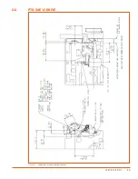
Page 21: ...13 Specifications 2 6 PTO SAE A DRIVE Figure 2 5 Power Take Off Auxiliary Drive Specs ...
Page 22: ...14 Specifications ...
Page 32: ...24 Component Description ...
Page 44: ...36 Installation and Operation ...
Page 58: ...50 Troubleshooting ...
Page 125: ...117 Parts Catalog ...
Page 134: ...NOTES ...
Page 135: ...NOTES ...

