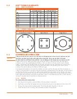
44
MAINTENANCE
3.
Clean oil return line and orifice.
4.
Install service air piping and reconnect all tubing. When replacing the oil return siphon tube, allow it to
contact the bottom of the sump tank then back off no more than 1/16 inch.
NOTE!
If the separator element has to be replaced frequently because it is plugged, it is an indication that dirt is
entering the inlet system, the compressor oil filter is faulty, or the oil is breaking down. The complete inlet
system, starting with the air cleaner, and all joints in piping to the inlet valve, should be checked for leaks.
5.13
THERMAL VALVE
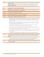
Inspect and clean the thermal valve if the unit shuts down because of high compressor discharge oil
temperature.
5.13.1 INSPECTION
Inspect the valve by removing it from the bypass housing. Sediment particles may lodge in the valve-seating
surface and prevent it from opening, thereby allowing hot oil to pass directly to the compressor without
being cooled.
5.14
OIL COOLER
The interior of the oil cooler should be cleaned when the pressure drop across the cooler at full load
exceeds 25 psi.
5.14.1 INSPECTION
Inspect compressor oil system for signs of varnish.
5.14.2 REMOVAL
1.
Drain compressor fluid.
2.
Remove oil cooler.
5.14.3 CLEANING
Circulate a suitable solvent to dissolve and remove varnish and sludge.
5.14.4 INSTALLATION
1.
Replace oil cooler and fill compressor with fresh oil.
2.
operate the machine normally for 50 hours. After 50 hours, change compressor oil and install a new oil
filter element.
5.15
COMPRESSOR SHAFT OIL SEAL
Check the compressor shaft seal for leaking oil every 1,000 hours or 6 months.
5.15.1 INSPECTION
Inspect the compressor shaft seal for signs of leaking oil.
NOTE!
If replacement is necessary, removal and installation instructions will be provided with the shaft seal kit.
5.16
CONTROL ADJUSTMENTS
The engine speed governor and pressure regulator are preset at the factory and normally require no
servicing. however, if it becomes necessary to make adjustments, use the following procedures:
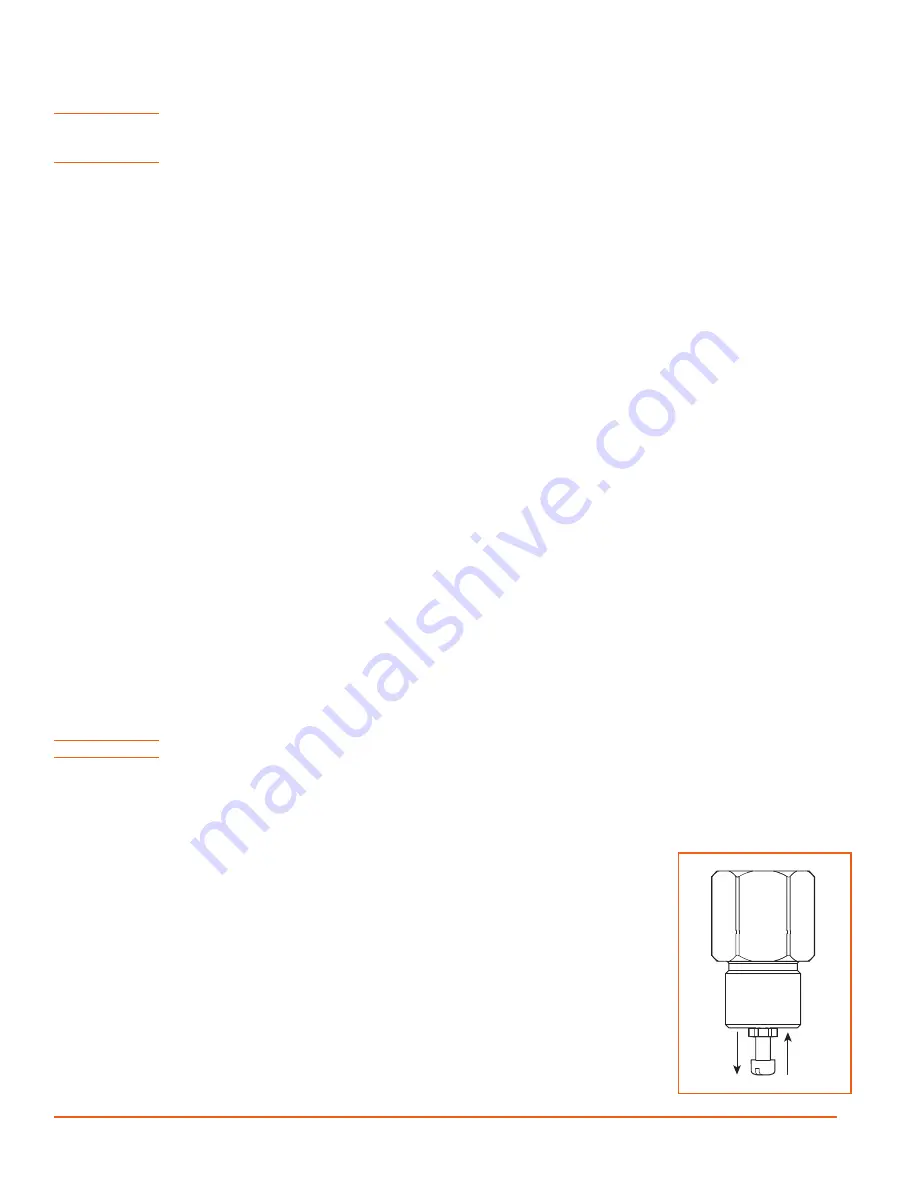
5.16.1 DISCHARGE PRESSURE ADJUSTMENT
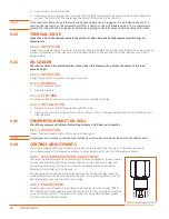
unit must be in RuN mode before adjusting. To increase pressure, loosen locknut
on pressure regulator adjustment screw and turn screw clockwise. lower the
operating pressure by turning screw counter-clockwise.
Reset locknut after
adjustment is completed. See
Check engine speed whenever pressure settings have been changed. only the
unloaded pressure can be selected with the pressure regulating valve. Full and
part load pressures are a function of air usage.
5.16.2 ENGINE SPEED
Engine speed is controlled by the Sullivan-Palatek Electronic Controller (SPEC).
The full load and idle speeds are programmed at the factory and there should be
no need for adjustment. If the machine is experiencing speed problems please
contact our Service Department.
RAISE
LOWER
Figure 5-4.
PRESSURE REGULATING VALVE
Summary of Contents for D260UJD4PTOW
Page 4: ......
Page 6: ...vi About This Manual ...
Page 14: ...6 Safety ...
Page 21: ...13 Specifications 2 6 PTO SAE A DRIVE Figure 2 5 Power Take Off Auxiliary Drive Specs ...
Page 22: ...14 Specifications ...
Page 32: ...24 Component Description ...
Page 44: ...36 Installation and Operation ...
Page 58: ...50 Troubleshooting ...
Page 125: ...117 Parts Catalog ...
Page 134: ...NOTES ...
Page 135: ...NOTES ...

