background image

16E / 16E-H / 16E-P Spray Gun

46

MAN 96150 EN 01

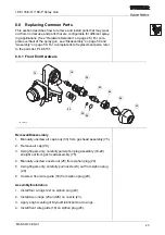
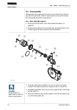
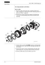
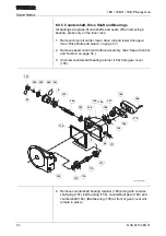
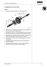
5. Carefully press nozzle (23) into front of siphon plug (20). Be care-

ful that nozzle o-rings are not twisted or torn and ensure that noz-
zle shoulder is flush with front of siphon plug.

6. Install nozzle nut (28) on siphon plug (20) and tighten firmly by 

hand.

7. Carefully press siphon plug assembly (18-28) into gas head 

assembly (75). Twist slightly and align cutouts in siphon plug 
flange with pins on gas head assembly. You should feel each 
siphon plug o-ring slip into the bore. The siphon plug is fully seated 
when the gas head pins extend slightly beyond the siphon plug 
flange.

8. Install air cap (29).

9. Install air cap body (33) on gas head assembly (75) and tighten 

firmly by hand.

Summary of Contents for 16E

Page 1: ... Sulzer Metco June 2009 16E 16E H 16E P Spray Gun Combustion Wire Spraying Product Manual MAN 96150 EN 01 ...

Page 2: ...Sulzer Metco US Inc 1101 Prospect Avenue Westbury NY 11590 1 516 334 1300 1 516 338 2414 www sulzermetco com ...

Page 3: ...al is intended to ensure safe and optimal operation of the 16E 16E H 16E P Spray Gun Keep this manual near your system Additional Documents 16E 16E H 16E P Spray Gun Parts List PL 96151 16E 16E H 16E P Spray Gun Spray Parameters PAR 96447 Copyright Restrictions The reproduction duplication or distribution of this manual in whole or in part by any means without prior written permission from Sulzer ...

Page 4: ...ally chapter 1 Safety before work ing with the 16E 16E H 16E P Spray Gun Sulzer Metco reserves the right to make improvements to the 16E 16E H 16E P Spray Gun without prior notice Chapter Intended Audience 1 Safety Everyone working with the spray gun 2 Product Description Everyone working with the spray gun 3 Installation Installation Engineers 4 Operation Everyone working with the spray gun 5 Tro...

Page 5: ... Rear Wire Guide and Snubber 19 2 3 Principles of Operation 20 2 3 1 Mechanical Operation 20 2 3 2 Combustion 20 2 3 3 Wire Feeding 21 2 4 Spray Gun Options 22 2 4 1 3XT Spray Gun Extensions 22 2 4 2 14EWGM Manual Wire Grip Mechanism 22 2 5 Auxiliary Equipment 23 2 6 Hardware Selection 26 2 6 1 Front End Hardware 26 2 6 2 Wire Guides Drive Rolls and Drive Gears 29 3 Installation 3 1 Exhaust System...

Page 6: ...nt End Hardware 45 6 8 2 Drive Rolls and Gears 47 6 8 3 Rear Wire Guide and Snubber 49 6 9 Disassembly 50 6 9 1 Wire Grip Mechanism 50 6 9 2 Gas Head Assembly 51 6 9 3 Handle and Wire Feed Valve 53 6 9 4 Speed Control and Turbine 54 6 9 5 Countershaft Drive Shaft and Bearings 56 6 9 6 Central Housing 58 6 10 Assembly 59 6 10 1 Countershaft Drive Shaft and Bearings 59 6 10 2 Speed Control and Turbi...

Page 7: ...ctions Whenever these symbols are encountered the user should read understand and proceed in accor dance with the definition provided below General Information and Warnings INFO Presentation of general but important information which must be read and understood prior to proceed ing CAUTION General hazard warning which can result in minor personal injury or minor damage to machinery WARNING Warning...

Page 8: ... footgear must be worn Keep hands hair clothing and tools away from moving parts Hazardous Materials and Conditions Explosion hazard explosive material present Strong electromagnetic fields present Flammable material or presence of high temperatures Poisonous substance present High voltage or risk of electric shock present High pressure warning Ultraviolet infra red or other damag ing light radiat...

Page 9: ...ould be thoroughly read and understood to ensure proper compli ance There are several basic precautions for thermal spraying which should always be observed These include good housekeeping proper mate rial gas storage and handling practices use and maintenance of equipment operator training sufficient exhausting of gases and fumes and personal protective equipment clothing ear eyes and breathing r...

Page 10: ...uct of the ventilation system should be vented to the outside of the building The combustion and HVOF spray processes generate carbon dioxide carbon monoxide NOx dust and fumes that can damage the respira tory system or cause death An adequate exhaust and ventilation sys tem is required A minimum air velocity of 90 m min 300 ft min is recommended in the areas adjacent to the spray gun and the obje...

Page 11: ...ble body of European standards that apply to the spraying of powders Electrical Power All electrical installations must be made in accordance with local and national code requirements All electrically powered equipment must always be properly grounded For additional information concerning electrical installations refer to the National Electric Code NFPA 70 or EN 60204 1 or applicable local electri...

Page 12: ...er in front of it It is dangerous and not recommended to use acetylene gas above 1 03 bar 15 psig Consult the local country regulations for maximum allowable acetylene pressures The following guidelines should be followed when handling gas tanks 1 Never drop tanks or knock tanks into one another Some gases are unstable e g acetylene even when in the tanks 2 Gas tanks should always be secured to a ...

Page 13: ...commended that pipe connections should be welded or brazed Gas piping should when possible be laid above ground and on the outside of the building Piping should not be laid in enclosed areas where gas leaks can accumulate such as above ceiling tiles or behind walls The piping installation must be checked for leaks and pressure tightness before putting it into service The piping installation should...

Page 14: ... held operation A tool post on the front of the spray gun provides for machine or tool mounting There are three versions of the spray gun 16E Standard 3 2 mm 1 8 and 2 3 mm 11 Ga wire Optional hardware available for wire size ranging from 4 8 mm 3 16 to 1 45 mm 15 Ga Standard fuel gas acetylene Other fuel gas propane natural gas MPS 16E H High Speed 3 2 mm 1 8 and 4 8 mm 3 16 soft wire such as bab...

Page 15: ...LPM 50 PSI at 195 SCFH Acetylene 1 03 bar at 21 9 NLPM 15 PSI at 50 SCFH Propane 3 45 bar at 18 4 NLPM 50 PSI at 42 SCFH MAPP MPS 3 45 bar at 17 5 NLPM 50 PSI at 40 SCFH Hydrogen 1 72 bar at 92 0 NLPM 25 PSI at 210 SCFH Wire Sizes 1 1 All wire sizes cannot necessarily be used with all gases See Hardware Selection on page 26 4 76 mm2 2 Wire sizes are listed in SI units for reference only Wires for ...

Page 16: ...t Descriptions 16e_subassy Drive Roll Carrier Wire Grip Mechanism Rear Wire Guide Snubber Turbine Speed Control Countershaft Bearing Assembly Gas Head Assembly with Safety Handle Valve Return Front End Handle with Wire Feed Control Central Housing Air O2 Fuel ...

Page 17: ...valve return spring When the safety handle is released the valve return will quickly close the gas head valve extinguish the flame and stop the wire from feeding The safety handle shall not be overridden or defeated The gas head assembly contains the spray gun front end hardware 2 2 2 Front End The front end hardware includes the front wire guide siphon plug nozzle nozzle nut air cap and air cap b...

Page 18: ...ear The upper drive gear engages the lower drive gear only when wire is being fed When the upper and lower drive gears engage the upper and lower drive rollers grip and feed the wire Although the air turbine is light weight and spins at very high speed up to 30 000 RPM the gear reduction results in a much lower speed and a much higher torque at the drive shaft The reduction ratio through the shaft...

Page 19: ...he WIRE FEED ON OFF control is an air valve that actuates the automatic wire grip mechanism If the manual wire grip mechanism is installed there is no wire feed control on the handle 2 2 7 Rear Wire Guide and Snubber The snubber allows the wire only to feed forward and prevents the wire from being pulled out the back of the gun The rear wire guide and snubber can be changed for different size wire...

Page 20: ... feed the wire The wire extends beyond the front of the air cap where it is fully melted and sprayed 2 3 2 Combustion The oxy fuel gas does not have enough energy even after combus tion to propel the melted material When the spray gun is initially lit with the gas head valve in the lighting position there is no air flowing to the front end Immediately after the gas is lit the gas head valve is set...

Page 21: ...the gun Wire feeding should always be stopped before closing the gas head valve If the safety handle is released while wire is feeding the flame will extinguish but the wire will not melt back to the proper point because the flame is also extinguished The wire will extend beyond the air cap Before relighting the gun trim the wire and position the end to slightly beyond the nozzle inside the air ca...

Page 22: ...rk piece surfaces that otherwise cannot be reached Some of the stan dard front end hardware is interchangeable with the extensions Angular air caps are also available for spraying inner bore diameters Refer to MAN 41526 2 4 2 14EWGM Manual Wire Grip Mechanism The manual wire grip mechanism replaces the standard automatic wire grip mechanism If the manual wire grip mechanism is installed there is n...

Page 23: ...imary air filter for thermal spray ing applications It removes moisture grease oil oil vapor and dirt from the compressed air supply line Refer to MAN 73102 6A Air Control Unit The 6A Air Control Unit is a pressure regulator and filter for the air sup ply to the thermal spraying system Refer to MAN 40400 3AF Air Flowmeter The 3AF Air Flowmeter controls and monitors the air flow to the ther mal spr...

Page 24: ...s to the combustion thermal spraying system Refer to MAN 40367 2W Wire Control Unit The 2W Wire Control Unit is a wire stand that holds a standard coil of bulk wire The 2W straightens the wire as it uncoils and feeds it to the gun under controlled tension Refer to MAN 87875 16e_3gr 16e_3gf SCF H OXY GEN 260 240 220 200 180 160 140 120 100 80 60 40 20 0 NLP M OXY GEN 110 100 90 80 70 60 50 40 30 20...

Page 25: ...lation must include an exhaust hood or plenum dust collector and a dedicated ventilation system The installation might also include an acoustical spray booth and one or more manipulators such as a lathe turntable or robot Acoustical Spray Booth Exhaust Hood Exhaust Plenum Dust Collector 16e_booth_vent ...

Page 26: ...he standard hardware is intended for spraying large areas where the wire is continuously fed Short duration spraying start stop operation may cause loading of material inside the air cap Non load air caps are intended to minimize material loading Softer wire with a lower melting point e g babbit tin etc may tend to stick in the nozzle during start stop operation Where rec ommended in the spray par...

Page 27: ... 3K3 JH 1000667 or 3K3 MH 1000668 12E7 30 1000276 3K3 JH 1000667 or 3K3 MH 1000668 Propane or Natural Gas 3 16 1 12E2 6 1000260 12E7 43 1000286 3K3 EA 1000666 12E7 43 1000286 3K3 AH 1000662 12E7 46 1000288 3K3 AH 1000662 5 32 12E2 6 1000260 14E7 52 1000320 3K3 EA 1000666 1 8 2 12E2 6 1000260 12E7 49 1000291 8E3 EC 1001570 12E7 49 1000291 3K3 CH 1000664 12E7 27 1000274 3K3 CH 1000664 11 Ga 12E2 6 1...

Page 28: ...hart Standard Air Cap Equivalent Non Load Air Cap Acetylene Propane MAPP 3K3 EA 1000666 3K3 AH 1000662 3K3 AM 1000663 8E3 EC 1001570 3K3 CH 1000664 3K3 CHM 1000665 4E3 J 1000835 3K3 JH 1000667 4E3 M 1000836 3K3 JH 1000667 1 1 If a smaller spray pattern is desired use 3K3 MH 1000668 in stead of 3K3 JH Operating pressure range of the gun will be re duced Depending on wire being sprayed and spraying ...

Page 29: ...up the rear wire guide and snubber assembly refer to parts list PL 96151 Upper Lower 3 16 1 8 5 32 11E23 1000160 11E118 1000139 11E32 1000169 5E35 316 1001103 5E36 1001104 1 8 11 Ga 12E23 18 1000258 12E118 18 1000247 12E32 18 1000264 4E35 18 1000832 4E36 1000833 15 Ga 12E23 15 1000257 14E118 15 1000246 12E32 18 1000264 4E35 15 1000831 4E36 1000833 18 20 Ga 12E23 15 1000257 14E118 15 1000246 12E32 ...

Page 30: ...starved Under some conditions metal dusts can be quite hazardous For this reason the exhaust system should be laid out by an experienced engineer For most installations a dust collector especially designed for metallizing dust should be installed Dust collectors designed primarily for other kinds of dust may be found to be very ineffective and in some cases dangerous if used for metal dust 3 2 Wir...

Page 31: ... illustration For a complete list of available hose packages refer to the parts list PL 96151 Instructions for auxiliary equipment identify the hoses that are required and optionally available for those components 5k_connect 3GF 3AF O2 Fuel 6A 16E Fuel Gas Oxygen 3GRO 3GRA 3GRP Fuel Gas Oxygen Air Air 2W Wire Compressed 4AC Air Supply ...

Page 32: ...o auxiliary equipment Tighten all fittings firmly but do not overtighten 3 Connect oxygen hose to spray gun first Then connect air and fuel gas hoses 4 One at a time open gas supply valves and regulators Check and correct for leaks Use a non residual leak check solution 5 Purge the spray gun Open the air supply regulator and set the spray gun gas head valve to the full run position Allow the gun t...

Page 33: ... setting the valve to the lighting position In the lighting position the valve allows only oxygen and fuel gas to flow to the nozzle Air flow remains off After the gun is lit the valve is immediately set to the run position The safety handle must be held for the valve to remain in the light ing position Run Normal operating position for spraying Fuel gas and oxygen are set to the optimum levels to...

Page 34: ...ition it inside the air cap just beyond the nozzle face WIRE FEED ON OFF Control Alternate action valve which starts and stops wire feeding Applies air pressure to actuate the wire grip mechanism causing the upper and lower drive rolls to grip and feed the wire Wire feeding is possible only when the gas head valve is in the run position Wire Speed Control Ring Varies the speed of the air turbine t...

Page 35: ...bine begins spinning up 7 Adjust 3AF flowmeter to value specified in spray parameters 8 If the spray gun has not been used for a long time rotate the speed control ring over its full range of travel approximately 5 full turns 9 Press WIRE FEED ON OFF control to start wire feeding and mea sure wire feed rate a If feed rate is not correct adjust wire speed control ring FASTER or SLOWER b Unlock snub...

Page 36: ...Service the gas head valve See Gas Head Assembly on page 51 6 Open fuel gas and oxygen tank valves 7 Adjust fuel and oxygen 3GR regulators to pressures specified in spray parameters 8 Open gas head valve to run position and engage safety handle Gases flow out of air cap and turbine begins spinning up Purge for at least 3 seconds 9 Adjust 3GF Gas Flowmeter for oxygen and fuel values specified in sp...

Page 37: ...feeding This will leave the wire tapered and make it easier to remove from the gun Trim the sharp tip of the wire before stowing the wire spool When spraying low melting point wires in occasional start stop opera tion the standard nozzles and air caps are satisfactory However fre quent starts and stops may cause these parts to load with sprayed metal If loading occurs or if the wire sticks in the ...

Page 38: ...oating of lubricant to aid in feeding through the nozzle Dust or dirt on the wire will accelerate wear of the nozzle and wire guides Always leave the original tag on the wire spool so that the wire can be identified 5 2 Difficult Lighting Possible Causes Damaged or dirty nozzle and or siphon plug Damaged or loaded air cap Damaged or obstructed hoses Plugged valve core bleeder holes Corrective Meas...

Page 39: ...backfire makes it necessary to clean the siphon plug and nozzles It may also cause the nozzle nut to loosen Replace damaged components 5 4 Sticking Wire Symptom Feeding stops Possible Causes Loading of soft wire Kinked or bent wire Metal shavings in the nozzle Corrective Measures Select non loading hardware See Hardware Selection on page 26 If the wire melts into the end of the nozzle it can usual...

Page 40: ... seal Fuel Gas Wire Size Lighting Pressure Lighting Flows 3GF Flowmeter Reading Oxygen Fuel Oxygen Scale Acetylene Scale bar PSI bar PSI NLPM SCFH NLPM SCFH Acetylene 3 16 2 6 38 1 15 19 29 46 64 1 2 3 5 1 8 2 6 38 1 15 19 29 46 64 1 2 3 5 11 ga 1 7 25 1 15 15 22 36 50 1 2 3 5 15 ga 1 7 25 1 15 14 20 34 48 1 2 3 5 Propane 3 16 2 9 42 2 6 38 24 32 55 72 2 3 4 7 1 8 3 2 47 2 9 42 24 32 55 72 2 3 4 7...

Page 41: ...re kit Do not wash the o rings with cleaning solvent Inspect them for dam age and replace them if necessary Do not stretch new o rings more than necessary Lubricate all o rings with Krytox before reassem bling the siphon plug Wipe any excess Krytox off the plug 6 3 Nozzles Whenever a nozzle is put on the gun the bore of the siphon plug should be wiped clean and a fresh film of Krytox put on the no...

Page 42: ... valve plungers are installed When replacing the o rings on the valve core install the o rings on the valve core dry Then apply a generous amount of Krytox to the entire surface of the valve core After servicing the valve core purge the spray gun thoroughly to clear any lubricant from the valve pas sages The three valve plungers in the hose block have radiused faces to mate with the curvature of t...

Page 43: ... plug up the hose Inspect and replace damaged hoses Do not overtighten hose fittings If a hose fittings is overtightened the stem in the male fitting may collapse This reduces the flow of gases and causes the same problems as obstructions in the hoses The gun end connections of the two gas hoses are most likely to be damaged If the hole in the stem is the correct size the back of a 43 drill 089 or...

Page 44: ... 1000 200 40 8 Clean nozzle Cleaning wire kit 1000 200 40 Clean siphon plug Cleaning wire kit 1000 200 40 Oil upper drive roll bushing 2 drops 1000 200 40 Oil upper drive roll carrier hinge 1 drop 1000 200 40 Lube turbine cover bearing Gearlube 1 5mm strip 1000 200 40 Check lubricant in gear case 1000 200 Clean turbine brake disc and shoe Do not lube Cleaning solvent 1000 200 Clean and lubricate c...

Page 45: ... Hardware Removal Disassembly 1 Manually unscrew air cap body 33 from gas head assembly 75 2 Remove air cap 29 3 Using fingers only carefully pull siphon plug assembly 18 28 straight out from gas head assembly 75 4 Manually unscrew nozzle nut 28 from siphon plug 20 5 Using fingers only carefully pull nozzle 23 out from siphon plug 20 6 Unscrew front wire guide 18 from siphon plug 20 Assembly Insta...

Page 46: ...iphon plug 20 and tighten firmly by hand 7 Carefully press siphon plug assembly 18 28 into gas head assembly 75 Twist slightly and align cutouts in siphon plug flange with pins on gas head assembly You should feel each siphon plug o ring slip into the bore The siphon plug is fully seated when the gas head pins extend slightly beyond the siphon plug flange 8 Install air cap 29 9 Install air cap bod...

Page 47: ... of drive roll carrier 4 Remove three screws 111 securing upper drive roll 108 to upper drive gear 110 Upper Drive Roll Gear Assembly Installation 1 Assemble upper drive roll 108 to upper drive gear 110 and secure with three screws 111 2 Install upper drive roll 108 and upper drive gear 110 in drive roll carrier 104 and slide drive roll axle 105 through drive roll carrier and center of gear and ro...

Page 48: ... drive shaft 173 buy turning gear clockwise toward front of spray gun 3 Once loose manually unscrew lower drive gear 123 from drive shaft 173 and remove 4 Repeat steps 1 3 for lower drive roll 124 Lower Drive Roll Gear Installation 1 Place lower drive roll 124 onto drive roll tool 184 reach inside cavity of central housing 129 and thread lower drive roll onto drive shaft 173 2 Use fingers to threa...

Page 49: ...and compression spring 7 Assembly Installation 1 Assemble wire guide snubber 3 snubber spring housing 5 roller 6 and compression spring 7 2 Install spring retainer 8 on wire guide snubber 3 and secure with set screw 9 Make sure set screw seats within channel in wire guide snubber 3 Install wire guide and snubber assembly 3 8 in central housing 129 and secure with set screw 10 Make sure set screw s...

Page 50: ... Remove three screws 118 securing wire grip mechanism to cen tral housing 129 and remove wire grip mechanism 3 Unscrew and remove cylinder 113 Do not remove or adjust screw 112 unless necessary to replace screw or o ring 121 4 Pull piston assembly 114 116 out from support block 119 along with spring 117 5 Remove retaining ring 114 from piston rod 116 and remove pis ton 115 from piston rod 16e_wire...

Page 51: ... the valve core form being removed If you remove the valve core with the valve plungers installed the valve core valve plungers 95 98 and o rings 96 97 may be damaged 1 Remove two screws 102 and 103 securing hose block 101 to gas head 85 and remove hose block from gas head 2 Remove compression springs plungers and associated o rings 83 94 100 from gas head 85 CAUTION DO NOT remove the valve core w...

Page 52: ...ut of end cap 77 and carefully release tension by allowing torsion ring 79 to rotate clockwise 1 2 turn 7 Remove end cap 77 torsion ring 79 torsion spring 81 and spring bushing 80 8 Remove screw 93 securing safety handle 92 to pawl and shaft assembly 84 slide out pawl and shaft assembly and remove safety handle 9 Remove screw 90 securing valve handle 89 to valve core 82 and remove valve handle com...

Page 53: ...sembly to central housing 129 3 Remove cam follower 181 from valve block 179 4 Remove valve shaft 177 and valve spring 178 from valve block 179 Accessing Lower Turbine Cover Screw To access the lower screw for the turbine cover the handle and wire feed valve do not need to be removed Remove only the cam follower 181 valve shaft 177 and valve spring 178 from the valve block 179 16e_handle 120 177 1...

Page 54: ...s 156 securing speed control assembly 137 144 to central housing 129 and remove speed control assembly 3 Rotate control ring 142 in SLOWER direction to unthread spider assembly 144 from control ring 142 until spider assembly can be removed 4 Remove three screws 138 and disassemble nameplate 139 detent spring 141 control ring 142 and turbine cover 143 5 Remove oil filter plug 137 from turbine cover...

Page 55: ...nd remove turbine assembly 145 154 from central housing 129 4 Remove shaft bearing retainer nut 145 from turbine shaft 154 and remove finger spring bearing washer brake disc return spring and disc brake 146 150 from turbine shaft 5 Remove set screw 9 securing turbine rotor 151 to turbine shaft 154 and remove turbine rotor from turbine shaft 6 Slide turbine seal 152 off turbine shaft 154 169 170 16...

Page 56: ...on page 47 2 Remove speed control and turbine assembly See Speed Control and Turbine on page 54 3 Unscrew countershaft bearing retainer 160 from gear cover 165 4 Remove countershaft bearing retainer 160 along with counter shaft plug 157 ball bearing 159 countershaft gear 162 and countershaft 164 Ball bearing 159 at front of gear cover will remain in place 16e_countershaft 157 160 161 22 158 159 15...

Page 57: ... nut 158 from drive shaft 173 9 Remove four screws securing gear cover 156 to central housing 129 and remove gear cover and gasket 176 10 Remove plug 171 from front of gear cover 156 11 Only if necessary for replacement remove two ball bearings 159 and one bearing 166 from gear cover 156 12 Remove drive shaft assembly 9 172 174 and drive shaft seal 175 from central housing 129 13 Disassemble drive...

Page 58: ... be disassembled unless absolutely necessary to replace parts The housing pump 130 requires critical alignment with the countershaft This alignment can only be done properly by Sulzer Metco as part a factory overhaul CAUTION Do not remove housing pump from central housing 129 130 131 132 133 16e_central_housing ...

Page 59: ...Press bearing 174 onto drive shaft 173 up to bushing b Install drive shaft gear 172 on drive shaft 173 with gear teeth against bushing and secure with set screw 9 Make sure set screw enters countersink on shaft 2 Install drive shaft assembly 9 172 174 and drive shaft seal 175 in central housing 129 3 Press ball bearing 159 in inside front of gear cover 156 16e_countershaft 157 160 161 22 158 159 1...

Page 60: ...re with set screw 9 Make sure set screw enters countersink on shaft 11 Install o ring 161 on countershaft bearing retainer 160 12 Assemble countershaft assembly 9 162 164 and countershaft bearing retainer 160 Press ball bearing 159 onto countershaft assembly and secure with nut 158 Hold countershaft assembly with glove or cloth and tighten nut 13 Install countershaft plug 157 with o ring 22 in cou...

Page 61: ...t screw 9 Make sure set screw enters countersink on shaft 4 Install disc brake 150 onto turbine shaft 154 so that spring clips engage button weights of governor spring on rotor 151 5 Install spring 150 and washer 148 with cupped side of washer facing spring 6 Install bearing 147 and finger spring 146 so that fingers of spring face bearing 7 Install shaft bearing retainer nut 145 on turbine shaft 1...

Page 62: ...octite 587 Blue or equivalent to both sides of gasket 170 11 Install bearing follower 167 gasket 170 and bearing cover 168 and secure with two screws 169 12 Fill central housing 129 with exactly 30 ml 1 fluid ounce of Gearlube See Countershaft Bearing Lubrication on page 42 13 Install oil plug 127 with o ring 128 in back of central housing 129 169 170 168 165 158 167 154 127 129 16e_turbine_remove...

Page 63: ...er assembly Be careful not to cross threads 3 Apply a light coating of Krytox to detent spring 141 Install detent spring and nameplate 139 with detents engaging notches in control ring Align holes and secure detent spring and name plate with three screws 138 Test control ring operation after tightening screws 4 Install speed control assembly 137 144 onto central housing 129 and secure with three s...

Page 64: ...er 181 in valve block 179 While actuating the valve shaft 177 tighten the cam follower until it engages the cam and can be made flush with the valve block After tightening all the way back off turn and test valve operation 5 Install two o rings 121 on valve block 179 6 Install rear handle 182 and wire feed valve assembly on central housing 129 and secure with two screws 91 7 Install front handle o...

Page 65: ...tire surface of valve core 82 3 Carefully install valve core 82 through right side of gas head sub assembly 85 1 Install compression spring 87 detent pin 88 and valve handle 89 on valve core 82 and secure with screw 90 2 Install pawl and shaft assembly 84 through gas head subassem bly 85 and safety handle 92 Secure safety handle to pawl and shaft assembly with screw 93 16e_gas_head 74 94 83 83 75 ...

Page 66: ...d cap pin 78 into end cap 77 Make sure the end cap pin is oriented so that the hole in end cap pin will line up with the hole in end cap Once the end cap pin is all the way through the valve core shaft release the torsion ring 10 Using a small screwdriver align holes in end cap pin 78 and end cap 77 and install screw 76 11 Install torsion ring cover 75 and secure with three screws 74 12 With spray...

Page 67: ...el gas and oxygen plungers 98 17 Install fuel gas and oxygen plungers 98 in gas head subassem bly 85 18 Install three compression springs 100 over plungers 95 98 in gas head subassembly 85 19 Install three o rings 85 in valve block 101 20 Install valve block 101 on bottom of gas head subassembly 85 and secure with two screws 102 and 103 ...

Page 68: ... 116 and secure with retain ing ring 114 4 Install piston assembly 114 116 and spring 117 into support block 119 5 Install Unscrew and remove cylinder 113 with screw 112 and o ring 121 6 Install wire grip mechanism on central housing 129 and secure with three screws 118 7 Install drive roll carrier See Drive Rolls and Gears on page 47 16e_wire_grip 112 113 114 115 116 117 118 119 120 121 122 121 1...

Page 69: ...g 34 controls 33 copyright restrictions 3 countershaft assembly 59 description 18 disassembly 56 D description 14 dimensions 15 disassembly 50 countershaft drive shaft bearings 56 gas head assembly 51 handle and wire feed valve 53 speed control and turbine 54 wire grip mechanism 50 drive gears removal replacement 47 selection 29 drive roll carrier 19 drive rolls removal replacement 47 selection 29...

Page 70: ...1 removal replacement 45 selection 26 O operating controls 33 operating procedures 35 operation 33 optional equipment 22 P personal protection 8 10 principles of operation 20 process gases 15 product description 14 R rear wire guide description 19 removal replacement 49 removal replacement 45 drive rolls and gears 47 front end hardware 45 rear wire guide and snubber 49 requirements 15 run position...

Page 71: ... technical data 15 troubleshooting 38 avoiding trouble 38 difficult lighting 38 flashback backfire 39 sticking wire 39 turbine assembly 61 description 18 disassembly 55 V ventilation and exhaust 10 W weight 15 wire care and use 38 feed rate 15 feeder 24 30 sizes 15 speed control 34 sticking 39 WIRE FEED ON OFF control description 19 operation 34 wire feed valve assembly 64 disassembly 53 wire grip...

Page 72: ...72 MAN 96150 EN 01 16E 16E H 16E P Spray Gun This page intentionally left blank ...

Reviews: