Página 17 de 19
CONTROL PANEL SULZER APC 1/2B
USER GUIDE
Rev.13 (2018/08/30)
ALARM SIGNALING AND PUMPS/PIT STATES SHOWN IN THE CONTROL PANEL
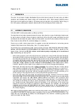
Activating the alarm float and motor control element of each pump are indicated by pilots in the
diagram of the well in the cabinet door
.
Any alarms that occur in the system (pumps, well, sensor, etc..) And detect PC 242 is indicated in the
user interface of the controller with the corresponding alarm text and, if reset pending, is also signalled
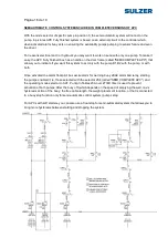
by activation of a potential free contact for general alarm (AL box terminals: 3 to AL: 5). Thus a picture
1/2B APC has 3 potential free contacts for remote signalling: 1 alarm per pump and 1 to indicate that
PC 242 has an alarm / s pending reset. This can be seen easily in the extract of the wiring diagram in
the following figure.
APC offers power output buzzer / light alarm ABS 9000056 or similar. As you can see in the figure
above, connect the warning signal or you can use the floating signal is desired along with the terminals
AL: + and AL: - Power to 24VDC.
The alarm output contact type controller is switched, having a closed contact between terminals 28 and
27 PC242 (called AL: AL 3 and 4 in the table). This output is programmed to switch if there is no alarm
on it so that if a device is connected alarm signalling (acoustic / light, picture, etc..) Indicate an alarm
both as a power failure or breakdown in PC242 (for would contact their state of rest: NC).


