15
8.2
Mounting of new stator
J 205, J 405:
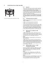
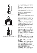
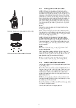
(Figure 22, 23) Block up the new sta-
tor and make sure that the motor housing can be fully
pushed down onto the stator. Protect the stator insula-
tion from damages and fold stator cables together in
two groups and put them into a position so they can
easily be pulled up through the holes/openings in the
motor housing when stator is mounted. Avoid cables
to get in contact with the hot motor housing during as-
sembly. Make sure the motor housing is secured by the
lifting crane and that it can be fully lowered on to the
stator.
Use Two LP-gas flames to heat the housing till about
198º to 250ºC (388º to 482ºF). With two 25 mm nozzles
this will take about one minute.
Rotate the motor housing into a position, so the sta-
tor/ thermal/control cables can be pulled up smoothly
through the motor housing and later pulled through and
assembled on the terminal plate/upper bearing bracket.
A stator lifting tool may be used for an alternative way
to lift back the new stator into the motor housing.
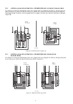
Check section 11 for part No. (Figure 22)
When the stator has been mounted the motor housing
may be cooled by compressed air.
Grease and mount the o-ring for the upper bearing in
the upper part of the motor housing on J 205.
J 604:
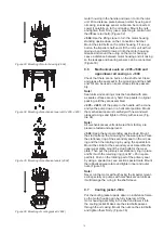
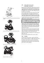
(Figure 22, 24, 25) Block up the motor housing
and make sure that the new stator can be fully lowered
into the motor housing. Protect the stator insulation
from damages and fold stator cables together in two
groups and put them into a position so they can easily
be pulled up through the holes/openings in the motor
housing when stator is mounted. Avoid cables to get
in contact with the hot motor housing during assembly.
Make sure the stator is secured by the lifting crane and
that it can be fully lowered into the motor housing.
Use Two LP-gas flames to heat the housing till about
198º to 250ºC (388º to 482ºF). With two 25mm nozzles
this will take about one minute.
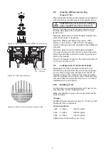
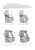
Rotate the stator into a position, so the two threaded
holes used by the locking key are placed on each side
of the axial groove in the motor housing (2xMC6S).
(Figure 25)
A stator lifting tool is used to lift back the new stator into
the motor housing. Check section 11 for part No. (Fig
-
ure 22)
When the stator has been mounted the motor housing
may be cooled by compressed air.
Grease and mount the o-ring for the upper bearing in
the upper part of the motor housing.
Figure 23: Mounting of Stator (J 205, J 405)
Figure 24: Mounting of Stator (J 604)
Figure 25: Axial groove in the motor housing (J 604)
Summary of Contents for J 205
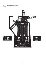
Page 30: ...30 11 Sectional drawing Tools J 205 ...
Page 31: ...31 J 405 ...
Page 32: ...32 J 604 ...
Page 37: ...37 ...


