background image

2

Workshop manual

XJ 25 - 110, XJC 50 - 110, XJS 25 - 110 

The manufacturer reserves the right to alter specifications due to technical developments !

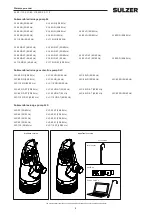
Submersible drainage pump XJ

XJ 25 ND (50/60 Hz) 

XJ 25 HD (50/60 Hz)

XJ 40 ND (50/60 Hz) 

XJ 40 HD (50/60 Hz)

XJ 50 ND (50/60 Hz) 

XJ 50 HD (50/60 Hz) 

XJ 50 LD (50/60 Hz)

XJ 80 ND (50/60 Hz) 

XJ 80 HD (60 Hz)  

XJ 80 LD (50/60 Hz)  

XJ 80 SD (50/60 Hz)

XJ 110 ND (50/60 Hz) 

XJ 110 HD (50/60Hz)

 
XJ 25 ND AT (50/60 Hz) 

XJ 25 HD AT (50/60 Hz)

XJ 40 ND AT (50/60 Hz) 

XJ 40 HD AT (50/60 Hz)

XJ 50 ND AT (50/60 Hz) 

XJ 50 HD AT (50/60 Hz) 

XJ 50 LD AT (50/60 Hz)

XJ 80 ND AT (50/60 Hz) 

XJ 80 HD AT (60 Hz)  

XJ 80 LD AT (50/60 Hz)  

XJ 80 SD (50/60 Hz)

XJ 110 ND AT (50/60 Hz) 

XJ 110 HD AT (50/60 Hz)

Submersible drainage center-line pump XJC

XJC 50 ND (50/60 Hz) 

XJC 50 HD (50/60 Hz) 

XJC 50 LD (50/60 Hz)

XJC 80 ND (50/60 Hz) 

XJC 80 HD (60 Hz)  

XJC 80 LD (50/60 Hz)  

XJC 80 SD (50/60 Hz)

XJC 110 ND (50/60 Hz) 

XJC 110 HD (50/60 Hz) 

 
XJC 50 ND AT (50/60 Hz) 

XJC 50 HD AT (50/60 Hz) 

XJC 50 LD AT (50/60 Hz)

XJC 80 ND AT (50/60 Hz) 

XJC 80 HD AT (60 Hz)  

XJC 80 LD AT (50/60 Hz)  

XJC 80 SD (50/60 Hz)

XJC 110 ND AT (50/60 Hz) 

XJC 110 HD AT (50/60 Hz) 

Submersible sludge pump XJS

XJS 25 (50/60 Hz) 

XJS 25 AT (50/60 Hz)

XJS 40 (50/60 Hz) 

XJS 40 AT (50/60 Hz)

XJS 50 (50/60 Hz) 

XJS 50 AT (50/60 Hz)

XJS 80 (50/60 Hz)  

XJS 80 AT (50/60 Hz)

XJS 110 (50/60 Hz) 

XJS 110 AT (50/60 Hz)

Standard version

AquaTronic version

Accessories

AquaPlug

Level sensor

Service Data Kit

Summary of Contents for XJ Series

Page 1: ...www sulzer com Submersible drainage pump XJ Submersible drainage center line pump XJC Submersible sludge pump XJS EN Workshop manual 00833219 AM 07 2019 ...

Page 2: ... Hz XJ 80 LD AT 50 60 Hz XJ 80 SD 50 60 Hz XJ 110 ND AT 50 60 Hz XJ 110 HD AT 50 60 Hz Submersible drainage center line pump XJC XJC 50 ND 50 60 Hz XJC 50 HD 50 60 Hz XJC 50 LD 50 60 Hz XJC 80 ND 50 60 Hz XJC 80 HD 60 Hz XJC 80 LD 50 60 Hz XJC 80 SD 50 60 Hz XJC 110 ND 50 60 Hz XJC 110 HD 50 60 Hz XJC 50 ND AT 50 60 Hz XJC 50 HD AT 50 60 Hz XJC 50 LD AT 50 60 Hz XJC 80 ND AT 50 60 Hz XJC 80 HD AT ...

Page 3: ...iffuser ND HD LD 12 4 2 1 Dismantling of diffuser 12 4 2 2 Assembly of diffuser 12 4 3 Impeller ND HD LD 13 4 3 1 Dismantling of impeller 13 4 3 2 Assembly of impeller 13 5 XJ 80 SD change of diffusers impellers and guide vane plate 14 5 1 Dismantling 14 5 2 Assembly 15 6 Primary seal and upper diffuser 17 6 1 Dismantling of primary seal and upper diffuser 17 6 2 Assembly of primary seal and upper...

Page 4: ...24 8 10 2 Change of AquaTronic connection interface 24 8 11 Assemble the top cover 25 9 Testing 25 10 Electrical information and wiring diagrams 26 10 1 Three phase Direct Start D O L with contactor 26 10 2 Three phase Direct Start D O L with AquaTronic 27 10 3 Three phase Soft Start with AquaTronic 28 10 4 Three phase Direct Start D O L with terminal block 29 10 5 Winding data 30 10 6 Fuses 31 11...

Page 5: ...ent maintenance and avoids unnecessary downtime for the pump The o ring kit is included in the repair kit and can be ordered separately For contents of repair and o ring kits see spare part lists positions marked 1 and 2 Repair kits XJ 25 40 XJS 25 40 00863347 XJ 50 110 XJC 50 110 XJS 50 110 00863348 O ring kits XJ 25 40 XJS 25 40 00863349 XJ 50 110 XJC 50 110 XJS 50 110 00863350 1 4 Tools The sub...

Page 6: ...ling Alu minium stainless steel ductile iron and high chrome cast iron can be recycled when a pump is scrapped Wear parts which consists of rubber polyurethane aluminium steel and cables stators with copper must be treated before recycling is possible Environmental white oil should be left to designated areas Workshop manual XJ 25 110 XJC 50 110 XJS 25 110 ...

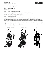
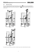
Page 7: ...ump starts by connecting it to the power supply 2 3 Dismantling cover Unscrew and lift off the cover and disconnect the power cables from the contactor terminal block If the water has penetrated through the cable gland and the cable seal the cable gland and the cable seal should be re placed Remove strain relief clamp prior to unscrewing cable gland body Pull out cable cable gland washer and unscr...

Page 8: ...00 V megohmeter megger and the reading should be at least 1 MΩ If the insulation resistance is lower the stator unit should be dried in an oven If the stator insulation reading after drying is still low the stator unit should be replaced See chapter 7 The insulation between the separate turns in the winding should also be checked This can be done by measuring the resistance of the phase windings w...

Page 9: ...are equipped with AquaTronic should be checked for continuity using an ohmmeter At 25ºC 47 kOhm The circuit used when pumps are equipped with DS contactor with the two thermal contacts TC1 TC2 T should be checked for continuity using an ohm meter or buzzer If one sensor has much too high or low resistance it should be removed from terminals at AquaTronic module ...

Page 10: ...heck 3 1 AquaTronic version See separate manual for Service Diagnostic Program 3 2 Standard version and AquaTronic version Unscrew the two oil plugs and drain off the oil in a clean can and inspect it Oil should be clear and without impurity For refilling of oil see chapter 8 9 The motor plug gives access to the motor housing Unscrew and check to make sure no oil or water has leaked into the motor...

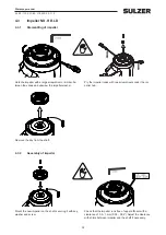
Page 11: ...1 1 Adjustment of wear ring m CAUTION Do not place the pump directly on the AquaTronic unit It will break Adjust the clearance with the three screws that hold the wear ring Check clearance between wear ring and impeller Clear ance should be less than 0 3 mm Loosen the wear ring to make adjustments Turn the pump upside down and remove the base plate and strainer Fasten wear ring with remaining thre...

Page 12: ...r ND HD LD 4 2 1 Dismantling of diffuser Remove the screws which hold the upper diffuser and bear ing house together Check the diffuser for scratches The rubber should have a smooth surface Fasten the upper diffuser on the bearing house 4 2 2 Assembly of diffuser ...

Page 13: ...w the impeller washer Mount the new impeller on the shaft securing it with key washer and screw 4 3 2 Assembly of impeller Remove the key from the shaft Pry the impeller loose with two screwdrivers under the im peller hub Check that the impeller runs free of upper diffuser with a clearance of 0 5 1 mm 0 02 0 04 Adjust the clearance with shims between impeller and the shaft if necessary ...

Page 14: ...the strainer and press against the diffuser Hold the impeller with a large screwdriver or similar be tween the vanes and unscrew the impeller screw with an 6 mm Allen key Turn the impeller so the three marks on the impeller side meet the channels of the guide vane plate Pry the lower impeller loose with screwdrivers on the marks of the impel ler sides Remove the key from the shaft If the impeller ...

Page 15: ...r is stuck hit it carefully in circles with a ham mer Check if there are shims on top of the upper impeller if so remove them too Mount the new lower impeller on the shaft securing it with the key spring washer and screw Check that the impel ler runs free of guide vane plate Adjust the clearance with shims between the tube distance and upper impeller if nec essary Put the shims on the shaft then t...

Page 16: ...nto each stud bolt Check that the distances are in place in the diffuser Grease and mount o ring on the oil casing Put the strainer in place and then the rubber sleeves and the base plate Tighten it up with the bottom nuts Workshop manual XJ 25 110 XJC 50 110 XJS 25 110 ...

Page 17: ... two screwdrivers Remove the stationary ring with o ring of the primary seal Remove the rubber foam and o ring in the bearing house 6 2 Assembly of primary seal and upper diffuser Mount stationary ring of primary seal with o ring in its seat in the bearing house Before the outer o ring is mounted on the bearing house check that upper diffuser is compressing the o ring in the stationary seal enough...

Page 18: ...n the bearing house Grease and mount o ring on the bearing house and mount upper dif fuser with screws Tighten gradually crosswise Grease and mount a new primary seal o ring on the shaft Oil the sealing surfaces of the mechanical seal and push the rotating ring onto the shaft ...

Page 19: ... pump and remove AquaTronic 7 1 2 Standard version Turn the pump and remove the contactor from the omega rail 7 2 Oil motor hydraulic primary seal and upper diffuser Perform all dismantling operation in chapter 3 5 then continue with 7 3 Secondary seal 7 3 1 Dismantling of secondary seal Remove circlip and rotating parts of secondary seal from the shaft Remove the stationary ring with two screwdri...

Page 20: ...circlip pliers diameter 25 mm and remove washer holding the bearing Place the rotor into a tube or similar of the same length as the rotor shaft and with an inner diameter slightly larger then the outer diameter of the bearing seat Press against the end of the shaft until the rotor comes loose The bear ing seat can be heated quickly with LP gas to facilitate the removal m If high pressure is neede...

Page 21: ...Stator 7 6 1 Insulation check Dry the stator unit in oven in not more than 80 90 C 176 194 F for at least 2 3 hours If the insulation resistance still is too low the unit should be replaced Arrange the motor cables so as to avoid jamming when the stator is falling out of the housing 7 6 2 Dismantling of stator Heat the motor housing with two LP gas flames large pro pane burner at the stator lamina...

Page 22: ...s to simplify disassembly during future overhaul 8 2 Assembly of ball bearings Clean the bearing house and all sealing surfaces thor oughly Remove burrs and scratches All ball bearings are sealed and pre filled with grease for lifetime performance Heat the bearing seat with LP gas to about 150ºC 302ºF and mount the bearing in the seat Mount the cirlip on top of the bearing Press upper bearing into...

Page 23: ...ed 8 4 Secondary seal Clean and grease the seal seat in the bearing house and mount the stationary ring with o ring Push it down to the bottom of the seat Push the rotating part of the secondary seal onto the shaft Mount the circlip and push it down till it fits into the grove m Always use new mechanical seals for assembly For repair kit part nos see chapter 1 2 8 5 Primary seal and upper diffuser...

Page 24: ...n the cable seal Push the cable seal in place in the top cover and tighten the screw Make sure that the washer is in place Connect the phases according the wiring diagram chapter 9 1 Yellow green earth screwed to cover 8 9 Refilling of oil Fill all the way up to entrance of oil inspection hole Make sure to fill in oil chamber marked with an oil drop Tighten the oil plug with a new o ring Use Paraf...

Page 25: ...cover with the screws 9 Testing Connect motor cable to power supply and start the pump If possible operate the pump in water and measure the head against closed valve Also make sure that the rotor is rotating in correct direction if the stator is changed repaired or the AT is changed With AT connect the AquaTronic USB interface cable 00863329 and make sure that a correct connection is established ...

Page 26: ...3287AA Figure 2 Direct start with contactor 230 460 V 10 Electrical information and wiring diagrams 10 1 Three phase Direct Start D O L with contactor The stators are wound for different voltages and can be internally Delta or Star connected The contactor is activated by the same voltage as the supply voltage Therefore when changing from one voltage to an other the contactor must also be changed ...

Page 27: ...COM TC1 TC2 NTC1 DI DI A2 A2 A1 A1 GR 24V BCK FWD WHITE ORANGE BLACK DI1 DI2 DI3 OUT3 OUT2 OUT1 L3 L1 L2 U1 6 5 3 4 2 1 230V 50Hz XJ 40 L2 L1 5 6 W1 3 4 V1 1 2 L3 L2 230V E A B D F G H C TCOM TC TC TC1 TC2 TU1 NTC NTC TV1 DI 00833372AA Figure 4 Direct start with AquaTronic 230 V 50 Hz XJ 40 00833285AA XJ 40 Figure 5 Direct start with AquaTronic 230 V 50 60 Hz XJ 40 10 2 Three phase Direct Start D ...

Page 28: ...6 5 4 3 2 1 U1 230V 50 60Hz 380V60Hz 400V 50hz 460V 60Hz W1 V1 U1 V1 W1 00833235AC Figure 6 Soft Start with AquaTronic 10 3 Three phase Soft Start with AquaTronic The stators are wound for different voltages and can be internally Delta or Star connected ...

Page 29: ...llel 460V Y serie V5 V1 BLUE 2 TU1 U2 TC BLUE 6 TC1 TC2 U1 3 NTC TV1 RED BLACK L3 W5 W2 L2 TC RED W1 BLACK TCOM 1 4 5 BLACK BLUE U5 V2 NTC L1 RED Gr TU1 TV1 TERMINAL BOARD DI 5 DI F1 F0 F1 Figure 7 Standard connecting for Direct Start D O L 230 V or 400 V 50 Hz RED BROWN YELLOW GREY GREEN BLACK BLUE Green Yellow TERMINAL BOARD MOTOR THERMAL PROTECTION 1 F0 2 3 4 5 6 F1 L1 L2 L3 F0 F1 U1 V1 W1 U2 W...

Page 30: ...3133 00863133 x2 x2 F Parallel Clockwise 1 3 72 0 9 3 6 7 230 460 DOL 00833297 00863297 x2 x2 F YY Clockwise 0 33 1 3 21 0 8 3x0 85 9 5 6 500 6 7 575 DOL 00833134 00863134 x2 x2 F Series Clockwise 2 1 45 2x0 80 3 5 6 690 00833509 00863509 x3 F Y Parallel Clockwise 3 7 72 0 9 6 5 6 1000 DOL 00833135 00863135 x3 F Y Series Clockwise 4 1 52 2x0 75 6 XJ XJS 80 9 8 230 DOL 00833136 00863136 x2 x2 F Par...

Page 31: ...4 A 9 0 3 3 XJ XJC 110 37 4 A 21 5 A 17 2 A 8 6 A 8 0 3 0 XJS 25 8 8 A 5 1 A 4 3 A 2 0 A 5 3 XJS 40 13 2 A 7 6 A 6 1 A 3 0 A 6 3 XJS 50 19 7 A 11 3 A 9 0 10 8 A 4 5 A 8 9 3 9 XJS 80 27 8 A 16 0 A 13 8 A 6 4 A 9 0 3 3 XJS 110 37 4 A 21 5 A 17 2 A 8 6 A 8 0 3 0 Three phase 60Hz Starting current factor Pump 230V 380 V 460V 575V Direct Start Soft Start XJ 25 9 8 A 5 9 A 4 9 A 3 9 A 6 0 XJ 40 14 8 A 8 ...

Page 32: ...al XJ 25 110 XJC 50 110 XJS 25 110 Stator Rotor and shaft Impeller Wear ring Bearing house Motor housing Ball bearing upper AquaTronic Contactor Ball bearing lower Lower diffuser Upper diffuser 11 Sectional drawing XJ ...

Page 33: ...33 XJS Stator Impeller Bearing house Volute Motor housing Ball bearing upper AquaTronic Contactor Ball bearing lower Diffuser Rotor and shaft Workshop manual XJ 25 110 XJC 50 110 XJS 25 110 ...

Page 34: ...otor Complete pump overhaul 1 8 Blocked impeller Check for stones pieces of wood etc Check diffuser for damages 4 2 8 8 Water intrusion See error Water found inside top cover and or motor housing Loose wires between motor contactor power cable Fasten wires and check for water intrusion Check cables in connection chamber 8 10 The motor trips out Pump overloaded due to material build up Hydraulic ch...

Page 35: ...ts and dry motor 5 7 Pump operating at too low capacity Worn or damaged impeller and or wear ring and or diffuser Hydraulic check 4 Residual Current Device trips out Moisture in stator Dry motor 1 8 12 3 Troubleshooting service inspection with Service Diagnostic Program for AquaTronic Error Probable cause Solution Chapter Workshop manual XJ 25 110 XJC 50 110 XJS 25 110 ...

Page 36: ...Sulzer Pump Solutions Ireland Ltd Clonard Road Wexford Ireland Tel 353 53 91 63 200 www sulzer com Copyright Sulzer Ltd 2019 ...

Reviews: