Version 3.07
| Optidrive P2 User Guide |
53
www.invertekdrives.com
Par
Parameter Name
Minimum
Maximum
Default
Units
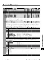
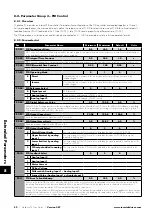
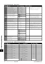
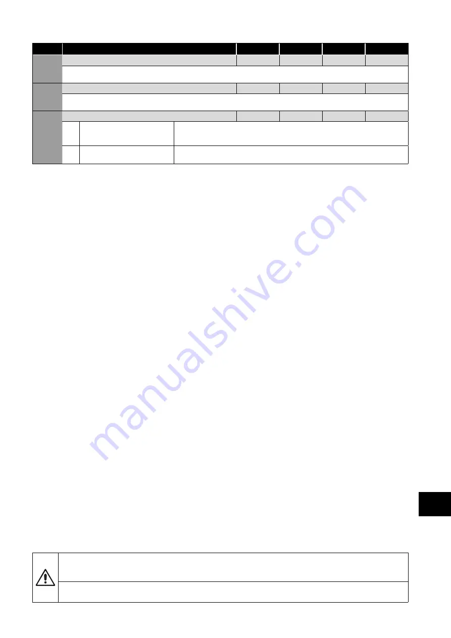
P3-12
PID Feedback Display Scaling
0.000
50.000
0.000
-
Applies a scaling factor to the displayed PID feedback, allowing the user to display the actual signal level from a transducer,
e.g. 0 – 10 Bar etc.
P3-13
PID Error Wake Level
0.0
100.0
5.0
%
Sets a programmable level whereby if the drive enters standby motor whilst operating under PID control, the selected feedback signal
must fall below this threshold before the drive will return to normal operation.
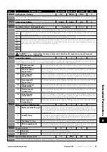
P3-18
PID Reset Control
0
1
1
-
0
Continuous operation
In this operating mode, the PID controller operates continuously, regardless of whether the
drive is enabled or disabled. This can result in the output of the PID controller reaching the
maximum level prior to the drive enable signal being applied.
1
Operate only when the
drive is enabled
In this operating mode, the PID controller only operates when the drive is enabled, and
hence will always start from zero when the drive is enabled.
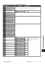
8.2.3. Parameter Group 4 – High Performance Motor Control
Overview
Parameters relating to the motor control are located together in Group 4. These parameters allow the user to:
Select the motor type to match the connected motor.
Carry out an autotune.
Define the torque limits and setpoint source for control methods that support this (vector control methods only).
Optidrive P2 can operate with both Asynchronous Induction Motors, the type most commonly seen today, and also some synchronous
motors. The sections below provide basic guidance on how to adjust the parameters to operate with the required motor type.
8.2.4. Asynchronous IM Motors
IM Motor Control Methods
IM Motors may be operated in the following modes:
V/F Speed Control (Default Mode)
o This mode provides the simplest control, and is suitable for a wide range of applications.
Sensorless Vector Torque Control
o This method is suitable for specific applications only, which require the motor torque to be the primary control function, rather
than speed, and should be used with extreme care only in specific applications.
Sensorless Vector Speed Control
o This method provides increased starting torque compared to V/F mode, along with improved motor speed regulation with
changing load conditions. This method is suitable for more demanding applications.
Operating in Sensorless Vector Speed Control Mode
Optidrive P2 can be programmed by the user to operate in Sensorless Vector mode, which provides enhanced low speed torque,
optimum motor speed regulation regardless of load and accurate control of the motor torque. In most applications, the default
Voltage Vector control mode will provide adequate performance, however if Sensorless Vector operation is required, use the
following procedure.
Ensure advanced parameter access is enabled by setting P1-14 = 101.
Enter the motor nameplate details into the relevant parameters as follows:
o P1-07 Motor Rated Voltage
o P1-08 Motor Rated Current
o P1-09 Motor Rated Frequency
o (Optional) P1-10 Motor Rated Speed (Rpm)
o P4-05 Motor Power Factor.
Select Sensorless Vector Speed Control mode by setting P4-01 = 0.
Ensure that the motor is correctly connected to the drive.
Carry out a motor data Autotune by setting P4-02 = 1.
The Autotune will begin immediately when P4-02 is set regardless of the status of the drive enable signal. Whilst the autotune
procedure does not drive or spin the motor, the motor shaft may still turn slightly. It is not normally necessary to uncouple the
load from the motor; however the user should ensure that no risk arises from the possible movement of the motor shaft.
It is essential that the correct motor data is entered into the relevant drive parameters. Incorrect parameter settings can
result in poor or even dangerous performance.
8
Extended P
arameters


