background image

9

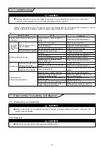
10. Troubleshooting

When any abnomality occurs in the reducer, refer to the following table and take appropriate measures as soon as
possible. If they are not repairable, contact the nearest agent, distributor or service office.

Details of trouble

The input shaft rotates, but the output
shaft will not.

Damage due to overloaded gears or
shafts

The key is out of position

Scorched bearing

Poor adjustment of protective device

Incorrect wiring for the motor

Overload

The ambient temperature is too high
Damage due to overload applied to
gears, bearings, etc.

Reduce the load to the specified value

Improve the ventilation method

Damaged gears, shafts, or bearings

Repair at a specialized workshop

Deformation of the housing due to
irregular installation surface

Flatten the installation surface or use
liners for adjustment

Repair at a specialized workshop

Damaged oil seal

Scratches or abrasion of the lip contact
section

Loose tightening bolt

Tighten the tightening bolts to the proper
torque

Change the oil seal

Repair at a specialized workshop

Repair at a specialized workshop

Place the key in position

Repair at a specialized workshop

Adjust the protective device

Change the connection

The output
shaft turns
when there is
no load.

Excessive temperature rise

Oil leakage

Abnormal sound.
Excessively high vibration.

Oil leaks from the input /
output shaft sections.

Oil leaks from the joint
surface of the housing.

But it seizes up when a
load is applied.

Reverse rotation is possible.

Cause

Correction

Scorched bearing

Repair at a specialized workshop

Resonance due to insufficient rigidity of
installation base

Reinforce the installation base to
improve the rigidity

Incorrect alignment with the mating machine

Align the shaft center

Transmission of the vibration of the
mating machine to the reducer

Independently operate the reducer to
check the source of abnormal sound

Table 8

11. Disassembly / reassembly and disposal

11-1)  Disassembly and reassembly

11-2)  Disposal

CAUTION

Repair, disassembly, and reassembly should be handled by properly trained technicians ; otherwise, the
system may be damaged.

CAUTION

CAUTION

Dispose the reducer and lubricant as general industrial waste.

Promptly identity and correct, according to instructions in this maintenance manual, any abnormalities
observed during operation. Do not operate until abnormality is corrected.

Summary of Contents for PARAMAX SFC Series

Page 1: ...y trained technicians Carefully read the maintenance manual before use Oil is removed from PARAMAX DRIVE FOR AIR COOLED CONDENSERS before shipment Supply oil according to the maintenance manual before...

Page 2: ...garding safety and proper use DANGER CAUTION The unit should be operated only within its design and performance specifications otherwise injury or damage to a system may occur Keep hands and all forei...

Page 3: ...tor Serial number Fig 1 Rating plate CAUTION Unpack the unit after verifying that it is positioned right side up otherwise injury may result Verify that the unit received is in fact the one ordered Wh...

Page 4: ...or damage to the equipment and or lifting device may result Before hoisting check the weight with the rating plate crate performance specifications catalog etc Never hoist a PARAMAX DRIVE FOR AIR COOL...

Page 5: ...n lbs 12390 21510 Install PARAMAX DRIVE FOR AIR COOLED CONDENSERS on a sufficiently rigid base Use installation bolts corresponding to JIS strength class 8 8 or its equivalent The torque of installati...

Page 6: ...Shaft Shaft end thread Fig 3 Fig 2 6 Lubrication 6 1 Shipping condition 6 2 Method of lubrication 6 3 Selection of lubricant Refer to Table 3 to select mineral oil or synthetic oil Table 4 shows recom...

Page 7: ...h a visual oil gauge Fig 4 Exercise care when supplying oil to ensure that loose nuts bolts washers dust water and other foreign substances will not enter the unit If oil level is lower than the speci...

Page 8: ...plug during operation otherwise splashing lubricant may cause burns When reversing the direction of rotation first bring the unit to a complete stop then commence reverse rotation otherwise the system...

Page 9: ...al operation is still not possible contact the nearest agent distributor or service office 1 Change oil 500 hours or 6 months whichever comes first after initial start up 2 In case of the oil temperat...

Page 10: ...hop Place the key in position Repair at a specialized workshop Adjust the protective device Change the connection The output shaft turns when there is no load Excessive temperature rise Oil leakage Ab...

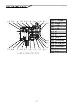
Page 11: ...on shaft Helical gear Helical pinion shaft Key Oil pump Key Key Key Key Tolerance ring Tapered roller bearing Tapered roller bearing Spherical roller bearing Spherical roller bearing Tapered roller be...

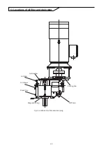
Page 12: ...11 Fig 6 Locations of oil filler and drain plug Oil Filler Oil Gauge Drain Plug Magunetic Plug Air Breather Oil Pump Cooling Fan 13 Locations of oil filler and drain plug...

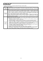
Page 13: ...God or any other reasons beyond the control of the Seller 8 waste exhaustion normal wear and tear or deterioration on the parts of the Products such as bearing oil seal 9 any other troubles problems...

Page 14: ...GM2202E 1 0 2004 2...

Reviews: