18
Common
5. Coupling with Other Machines
19
(5) Flange Mounted Option
[1] Mount the product on the driven shaft machine.
[2] Assemble the driven shaft on the hollow shaft.
[3] Assemble the bearing unit onto the driven shaft, and upon confirming that there is no shaft looseness, fix the bearing unit.
Note: Exercise caution to prevent the case from getting twisted relative to the driven shaft and the hollow shaft, which may result in exces-
sive force. Otherwise, the product and shaft bearing unit may be subjected to an unreasonable force, resulting in a damage of internal
parts.
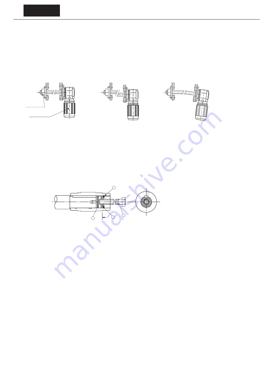
This product
Bearing unit
Good Example
Bad Example
The concentricity of the driven shaft
and the mounted spigot is not appropriate.
The perpendicularity of the driven shaft center
and the mounted ange surface is not appropriate.
Figure 5-15 Flange Mounted Example
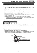
(6) Removing from the Driven Shaft
Be careful not to allow excessive force to apply between the case and the hollow shaft. Use a jig such as the one shown in Figure 5-16
to remove it more smoothly.
g
h
A
A〜
i
f
トルクアームの取付2
ⓕ
Spacer
ⓖ
Finished bolt
ⓗ
Disc
ⓘ
Retaining ring
Figure 5-16 Removal of Jig
Notes: 1. The removal jig and parts are to be prepared by the customer.
2. Refer to the catalog for recommended sizes.


