22
6. Wiring
23
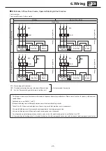
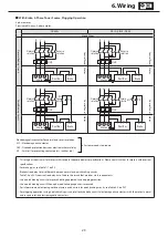
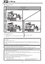
6-5 Motor Wiring
Showing page number having motor wiring diagrams.
Table 6-2 Without Brake
Motor Type
Capacity (kW)
Number of Lead
Wires
Page
Direct Input
from
Commercial
Power Source
Inverter Drive
3-Phase Motor
Standard
0.4 - 0.55
3
P23
P24
Increased safety
0.4 - 7.5
11 - 45
3
6
P23
-
Premium
-Efficiency,
3-Phase Motor
Standard
0.75 - 3.7
5.5 - 45
3
6
P23
P24
Increased safety
0.75 - 3.7
5.5 - 22
3
6
P23
-
AF Motor for Inverter
0.4
30 - 37
3
11
-
P24
Normal Braking Circuit
for Inverter Circuit
Premium-Efficiency,
3-Phase Motor
0.75 - 3.7
5.5 - 45
3
6
-
P24
Table 6-3 With Brake
Motor Type
Capacity (kW)
Brake Type
Number of Lead
Wires
Page
One-Direction
Rotation
Plugging
Rotation
Inverter Drive
3-Phase Motor
0.4
FB-05A1
5
P25
P29
P33
0.55
FB-1D
Premium-Efficiency,
3-Phase Motor
0.75
FB-1E
5
P25
P29
P33
1.1
FB-1HE
1.5
FB-2E
2.2
FB-3E
3.0
FB-4E
3.7
FB-5E
5.5
FB-8E
8
P26
P30
P34
7.5
FB-10E
11
FB-15E
15
FB-20
P27
P31
18.5 22 30
FB-30
37 45
ESB-250
ESB-250-2
P28
P32
P35
AF Motor for Inverter
0.4
FB-1D
5
-
-
P33
30 37
ESB-250
ESB-250-2
13
P36
Normal Braking Circuit
for Inverter Circuit
Premium-Efficiency,
3-Phase Motor
0.75
FB-1E
5
-
-
P33
1.5
FB-2E
2.2
FB-3E
3.7
FB-5E
5.5
FB-8E
8
P34
7.5
FB-10E
11
FB-15E
15
FB-20
18.5 22 30
FB-30
37 45
ESB-250
ESB-250-2
P35
Note 1. Brake type may differ depending on specification. Check the nameplate.
2. These diagrams above are for motors with standard Japanese domestic specifications. Please consult with us for motors with over-
seas specifications.


