


Operation & Maintenance Manual
1
Cyclo® HBB
Cyclo® HBB
Table of Contents
Safety Symbols 2
Safety Precautions 2
Disposal 2
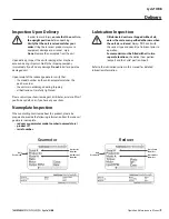
Delivery 3
Inspection Upon Delivery 3
Nameplate Inspection 3
Lubrication Inspection 3
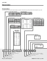
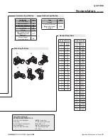
Nomenclature Inspection 4
Storage Location 6
Storage Period 6
Operation After Storage 6
Transporting 6
Installation Precautions 7
Installation Location 7
Installation Angle 7
Severe Loading Conditions 7
Installation onto the Driven Machine 7
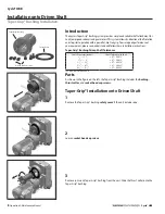
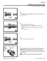
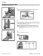
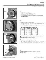
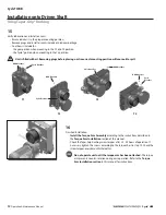
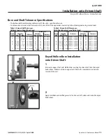
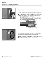
Installation onto Driven Shaft 8
Using Taper-Grip® Bushing 8
Keyed Hollow Bore Installation 13
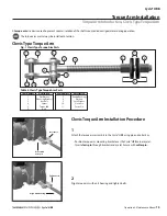
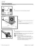
Torque Arm Introduction 15
Clevis Type Torque Arm 15
T-Type Torque Arm 17
Cyclo® HBB with Taper Grip Bushing 19
Cyclo® HBB with Keyed Hollow Bore 21
Determining Lubrication Method 22
Recommended Lubricants 24
Oil Quantities 25
Oil Fill/Drain Locations 26
Grease Quantities 27
Grease Replenishment/Drain Procedure 29
Cyclo® HBB Reducer 30
Cyclo® HBB Reducer Planetary Input (Ratios 11:1 and 18:1 Only) 33
Bearings and Oil Seals 34
Planet Gear Bearings (Reduction Ratios 11:1 and 18:1 Only) 35
Helical Gearing Tooth Count 35
Cyclo® HBB Screw Conveyor Option 36
Components 36
Assembly Instructions 37
Cyclo® Portion Disassembly/Assembly 40
Summary of Contents for Cyclo HBB
Page 1: ...0 7 6 0 1 6 0 0 0 3 H B B O M2 0 1 8...
Page 27: ...MA X MI N...


