Cyclo® HBB
Operation & Maintenance Manual
19
Cyclo® HBB
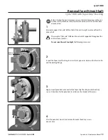
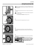
Removal from Driven Shaft
Cyclo® HBB with Taper-Grip® Bushing
Before starting the removal process, ensure that electrical power to the unit
has been safely locked out and electrical connections to the unit have been
disconnected
1
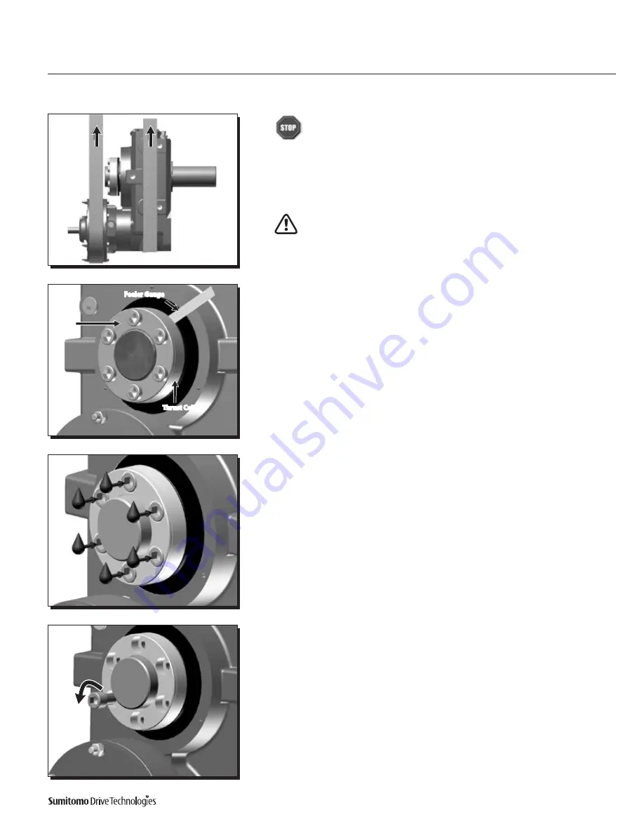
Externally support the Cyclo® HBB so that all the unit’s weight is removed from the
driven shaft
The weight of the Cyclo® HBB must be externally supported throughout the
entire removal process
Do not raise the unit too high!
Shaft binding may occur
2
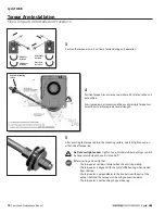
Inspect the Taper-Grip® Bushing to assure that a gap exists between the thrust collar
and the bushing flange
3
Apply a liquid-penetrant onto each of the Taper-Grip® Bushing socket-head cap
screws Allow time for the penetrant to settle into the threads of the screws
4
After the penetrant has settled, remove the socket head cap screws
one at a time
Bushing
Flange
1-3mm
Feeler Gauge
Thrust Collar
Summary of Contents for Cyclo HBB
Page 1: ...0 7 6 0 1 6 0 0 0 3 H B B O M2 0 1 8...
Page 27: ...MA X MI N...

