

Operation & Maintenance Manual
3
Cyclo® HBB
Cyclo® HBB
Delivery
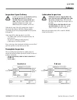
Inspection Upon Delivery
• In order to avoid injury,
ensure that the unit is in
the upright position
before unpacking.
•
Verify that the unit received matches your
order
Using the incorrect product may cause
equipment damage or personnel injury
•
Do not
remove the nameplate from the unit
Upon delivery, inspect the unit for damage that may have
occurred during shipment Notify the shipping company
immediately if you find any damage
Do not
install or operate a
damaged unit
Upon receipt of the reducer/gearmotor, verify that:
• the model number on the unit nameplate matches the
purchase order
• the unit was not damaged during shipping
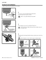
• all bolts and nuts are fully tightened.
Please consult your Sumitomo agent, distributor, or sales office if
you find any defects or if you have any questions
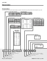
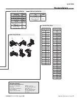
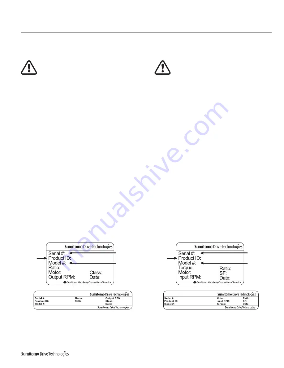
Nameplate Inspection
When contacting Sumitomo about this product, please be
prepared to provide the following information from the reducer/
gearmotor nameplate:
• reducer or gearmotor model number (nomenclature)
• product ID
• serial number.
Lubrication Inspection
•
Oil lubricated units are shipped without oil,
unless the customer specified otherwise when
the unit was ordered
Always fill the unit with
the correct type and quantity of lubricant prior to
operation
•
Some models must be filled with oil in two
separate locations,
the Helical Gear portion
(output) and the Cyclo® portion (input)
Refer to the lubrication section in this manual for detailed
lubrication information
Unit
Product ID
Unit
Product ID
Unit Serial
Number
Unit Model
Number
Unit Serial
Number
Unit Model
Number
Gearmotor
Reducer
Summary of Contents for Cyclo HBB
Page 1: ...0 7 6 0 1 6 0 0 0 3 H B B O M2 0 1 8...
Page 27: ...MA X MI N...


