background image

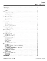
Operation & Maintenance Manual

 7


Cyclo® HBB

Cyclo® HBB

Installation Notes

Installation Precautions

•  Do not use the reducer/gearmotor for specifications 

other than those shown on the nameplate or in the 
manufacturing specification documents  Personnel 
injury and/or equipment damage may occur 

•  Do not place combustible material on or around 

the unit; fire may occur 

•  Do not place any objects around the unit that will 

prohibit proper ventilation  Inadequate ventilation 
may lead to high unit temperature and/or fire 

•  Do not step on or hang from the unit. Excessive 

weight may cause component breakage leading to 
personnel injury and/or equipment damage 

•  Do not touch the shaft, keyway, or motor fan with 

bare hands; injury may occur 

•  For applications in which lubricant leaks could 

adversely affect operations (i.e., package handling, 
food processing), place an oil pan below the unit to 
protect against contamination that may occur if oil 
seals become damaged or worn 

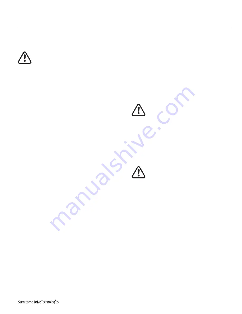
Installation Location

Ambient Temperature Range:  14 – 104°F (-10 – 40°C)
Ambient Humidity:  85% or less
Altitude:  3,280 feet (1,000 m) or less
Atmosphere: The location should not contain corrosive gas, 
explosive gas, or steam  The location should be free of dust and 
well ventilated 
Location: Indoor – free of dust and water

Consult Sumitomo when the unit will operate in conditions other 
than those specified above   Special unit modifications may be 
required 

Units manufactured according to customer specified application 
requirements (i e  outdoor modifications, high-temperature 
modifications) are designed to operate within the specified 
environment 

Install the unit so inspection and/or maintenance procedures may 
be easily performed  Install all units that are not shaft mounted 
on a sufficiently rigid base 

Installation Angle

You must mount the unit horizontally 

 Please consult Sumi-

tomo if the unit needs to be installed in a position other than 
horizontal 

If the unit was manufactured for a mounting position other than 
horizontal, 

do not mount it in a position other than the one 

specified 

Horizontal is the shaft orientation for standard units  Consult 
Sumitomo for shaft directions other than horizontal 

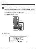
•  Do not remove the eye-bolt from the motor. Should 

you need to remove the eye-bolt for any reason, 
install a replacement bolt in the tapped hole to 
prevent water from entering the motor 

Severe Loading Conditions

For applications with severe vibration and/or frequent starts and 
stops, Sumitomo recommends the use of high-strength bolts of 
Grade 8 8 (or greater) to mount the reducer/gearmotor 

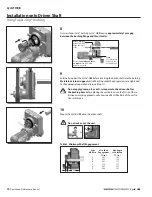
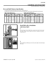
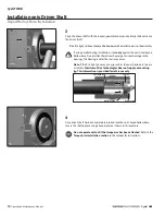
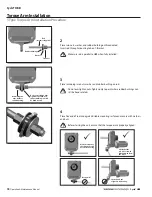
Installation onto the Driven Machine

•  Before mounting the reducer/gearmotor to the 

machine, verify the appropriate/desired rotation of 
the machine  Differences in the rotational direc-
tion may cause personnel injury and/or equipment 
damage 

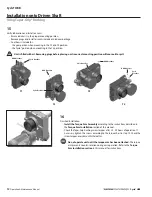
•  If a key is attached to the keyed hollow bore, tem-

porarily remove the key if the unit is not coupled to 
the driven machine and you wish to run the unit 

•  Before operating the unit, ensure that all safety 

guards around the rotating components are 
in-place and secure  Failure to do so may result in 
personnel injury 

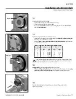
•  When joining the reducer or gearmotor to the load, 

ensure that the center alignment, belt tension, and/
or parallelism of the coupling device are within the 
coupling manufacturer’s established recommenda-
tions  For applications with a belt, ensure that the 
belt is properly tensioned to the manufacturer’s 
specification, and the bolts securing the pulley 
and couplings are sufficiently tightened  Failure to 
follow these precautions may result in personnel 
injury and/or equipment damage 

Summary of Contents for Cyclo HBB

Page 1: ...0 7 6 0 1 6 0 0 0 3 H B B O M2 0 1 8...

Page 2: ...ore Installation 13 Torque Arm Installation 15 Torque Arm Introduction 15 Clevis Type Torque Arm 15 T Type Torque Arm 17 Removal from Driven Shaft 19 Cyclo HBB with Taper Grip Bushing 19 Cyclo HBB wit...

Page 3: ...hly before use Understand the machine information on safety and all precautions for correct operation Sumitomo recommends that this manual is easily accessible for reference at the machine location On...

Page 4: ...y tightened Please consult your Sumitomo agent distributor or sales office if you find any defects or if you have any questions Nameplate Inspection When contacting Sumitomo about this product please...

Page 5: ...Cyclo HBB product code always E Motor Power Symbol 1750 RPM Frame Size Brake Ratio HP kW Symbol 1 8 0 1 01 1 4 0 2 02 1 3 0 25 03 1 2 0 4 05 3 4 0 55 08 1 0 75 1 1 5 1 1 1H 2 1 5 2 3 2 2 3 5 3 7 5 7...

Page 6: ...Ratio 364 424 501 578 683 809 956 1117 1320 1656 1957 2272 2559 2944 3 3511 7 4365 9 5177 9 6472 5 7228 7 8880 5 10568 1 12184 7 15530 3 17966 7 21620 9 26492 Y3 Y4 Y5 Y6 Type Suffix Standard High Ca...

Page 7: ...ambient conditions i e extreme temperatures UV rays Replace deteriorated parts with new ones before unit start up After starting the unit verify that there is no abnormal noise vibration and or tempe...

Page 8: ...ts that are not shaft mounted on a sufficiently rigid base Installation Angle You must mount the unit horizontally Please consult Sumi tomo if the unit needs to be installed in a position other than h...

Page 9: ...ent please read understand and follow these installation instructions Taper Grip Bushing Driven Shaft Tolerances Parts As shown in the figure on the left the Taper Grip Bushing includes the bushing th...

Page 10: ...checking for surface irregularities and fit Verify bushing bore size 6 Remove Taper Grip Bushing from driven shaft 7 Apply a thin layer of anti seize paste to the male threads of the Taper Grip bushi...

Page 11: ...l or anti seize paste to the driven shaft or the bushing bore before placing the unit onto driven shaft Use of these friction minimizing products will adversely affect the ability of the unit to trans...

Page 12: ...s been running for 20 to 30 hours re torque the screws to the values in Table 2 Screw torques should be subsequently checked at normal service intervals i e every 6 months 13 Apply grease to the expos...

Page 13: ...arm has been attached The torque arm prevents counter rotation during unit operation Refer to the Torque Arm Installation section in this manual for instructions 15 Verify lubrication and install air...

Page 14: ...0 0008 0 0001 55 65 0 021 0 002 C 2 7 16 3 0 0008 0 0001 60 75 0 021 0 002 D 2 3 4 3 1 8 0 0008 0 0001 70 80 0 021 0 002 3 3 16 3 7 16 0 0010 0 0001 81 85 0 025 0 003 E 3 3 16 3 15 16 0 0010 0 0001 80...

Page 15: ...he seals may occur Note If the fit is tight you may use a jig such as the one shown here to ease assembly Sumitomo Drive Technologies does not supply a mounting jig This information is provided for re...

Page 16: ...6 6 11 10 9 6 2 4 7 8 Item Number Description Item Number Description 1 Flat Washer 7 Rubber Bushings 2 Mounting Brackets 8 Washers 3 Hex Bolt 9 Lock Washer 4 Spacer 10 Clevis Pin 5 Torque Rod 11 Cot...

Page 17: ...ot over tighten nuts Tighten to point where rubber bushings can still be hand rotated when the unit is turned off Before starting unit verify that The torque arm will be in tension when the unit is op...

Page 18: ...ubber Bushings 4 Washers Cyclo HBB Rod Diameter Size Minimum Grade 8 8 Steel Z M12 A M16 B M20 C M24 D M24 E M30 Threaded Rod Nuts Mounting Bolt Mounting Bolt T bracket HBB Bolt Tightening Torque Size...

Page 19: ...e end of rod into rigid and stable mounting surface and secure with washers and nuts Before starting the unit ensure that the torque arm is properly aligned Rod customer supplied Rubber bushing Washer...

Page 20: ...e driven shaft The weight of the Cyclo HBB must be externally supported throughout the entire removal process Do not raise the unit too high Shaft binding may occur 2 Inspect the Taper Grip Bushing to...

Page 21: ...e against the bushing and clamp it against the shaft when the reducer is removed Apply a liquid penetrant to the shaft where it contacts the bushing Allow time for the liquid to penetrate between the...

Page 22: ...Do not raise the unit too high Shaft binding may occur 2 Carefully remove the shaft retaining device from the driven shaft 3 Apply a liquid penetrant to the shaft where it contacts the keyed hollow bo...

Page 23: ...efore start up Refer to the Lubrication Method section for details The unit must contain the correct type and amount of lubrication before operating For the Cyclo HBB the Cyclo and the helical gear po...

Page 24: ...ortion Oil D 6160DA 6165DA 6160DB 6165DB Cyclo Portion Grease Helical Gear Portion Oil E 6170 6175 6170DC 6175DC Cyclo Portion Oil Helical Gear Portion Oil E 6170DA 6175DA 6170DB 6175DB Cyclo Portion...

Page 25: ...pour point of the oil is lower than the ambient temperature at least with a 5C difference Use oil with a high viscosity index when the unit has a wide operating temperature range The oil should meet...

Page 26: ...4 44 4 2 9 51 9 0 7 4 7 0 Table 15 Double Reduction Cyclo Helical Gear Portion and Cyclo Portion Approximate Oil Quantity Units US liquid quart liter NOTE G Grease Lubricated Size Unit Unit Lubricatio...

Page 27: ...MA X MI N...

Page 28: ...ingle Reduction Cyclo Cyclo Portion Approximate Grease Quantity Units ounce gram NOTE L Oil Lubricated Maintenance Free Grease Model Size Unit Unit Lubrication Portion Mounting Configuration Y1 Y2 Y3...

Page 29: ...50 15 87 450 D6160DA D6165DA First Input 2 12 60 2 12 60 2 12 60 2 12 60 2 12 60 2 12 60 Second 26 46 750 26 46 750 26 46 750 26 46 750 26 46 750 26 46 750 D6160DB D6165DB First Input 4 23 120 4 23 12...

Page 30: ...se the grease temperature to rise or grease to leak into the motor Grease Replacement for Grease Lubricated and Maintenance Free Grease Models The unit may be safely operated for an extended time beca...

Page 31: ...nap Ring 7 High Speed Shaft A Bearing 8 Spacer 9 Cycloid Disc Spacer 10 Cyclo Eccentric Cam Assembly 11 Spacer 12 High Speed Shaft B Bearing 2 1 3 21 5 6 7 8 9 10 11 12 14 13 15 17 4 19 20 23 22 4 16...

Page 32: ...LG AP0020G 207 59 BQ421LG AP0021G 249 71 CN318LG AP0022G 305 87 CN257G AP0023G 417 119 CN259LG AP0024G A6100 A6105 21 6 AN9930G AP0025G 28 8 AN9931G AP0025G 39 11 AN9925G AP0026G 46 13 AN9926G AP0026G...

Page 33: ...75G 4 123 35 AN9381G AN7775G 4 151 43 AN9382G AN7775G 5 179 51 AN9383G AN7775G 5 207 59 AN9384G AN7775G 5 249 71 AN9385G AN7775G 6 305 87 AN9386G AN7775G 6 Model Reduction Ratio Part Numbers Overall C...

Page 34: ...lt Washer Nut Set 3 Gasket Set 4 Snap Ring 5 Ball Bearing 6 Spacer 7 Planet Gear Holder Plate 8 Sun Gear 9 Oil Slinger 10 Spacer 11 Snap Ring 12 High Speed Shaft B Bearing 2 1 3 21 22 23 19 7 8 9 10 1...

Page 35: ...G AN8318G AN8316G D6160 D6165 11 3 AP0890G AP0891G AP0889G 18 5 AN8323G AN8324G AN8322G E6170 E6175 11 3 AN8913G AN8914G AN8912G 18 5 AN8329G AN8330G AN8328G Bearings and Oil Seals Fig 11 Cyclo HBB Re...

Page 36: ...o Needle Roller Bearing Number Bearings perGear Total in Unit A6100 A6105 11 1 18 1 K 10 x 14 x 8 2 6 B6120 B6125 11 1 18 1 12R1620A 1 3 C6140 C6145 11 1 18 1 K 16 x 22 x 12 2 6 D6160 D6165 11 1 18 1...

Page 37: ...Adaptor Plate Shaft Collar Keeper Plate Seal Packing Material Z6090 Z6095 P P P P P P A6100 A6105 P P P P P P P P B6120 B6125 P P P P P P P P C6140 C6145 P P P P P P P P D6160 D6175 P P P P P P P P E6...

Page 38: ...the screw conveyor shaft completely into the Cyclo HBB output hub 3 Secure the screw conveyor shaft in place using the keeper plate with the supplied hardware 4 For units equipped with an adapter pla...

Page 39: ...f the screw conveyor adapter To seal the output portion of the screw conveyor adapter Sumitomo Drive Technologies provides two different options for each screw conveyor kit High Performance Braided Co...

Page 40: ...ation Maintenance Manual 39 Cyclo HBB Cyclo HBB Screw Conveyor Option Assembly Instructions 9 If using the braided cord seal tighten the gland cover bolts to achieve appropriate sealing on the screw c...

Page 41: ...n shaft by following the instructions outlined in the Removal From Driven Shaft section of this manual 3 While carefully supporting the entire unit place the unit on a level work surface so that the h...

Page 42: ...the pins on the pin carrier to see if any of the rollers have adhered to them 7 Remove the snap ring the ball bearing and the spacer from the high speed shaft 8 Using both hands lift out the top Cycl...

Page 43: ...Procedure 10 Remove the eccentric bearing from the high speed shaft 11 Using both hands carefully remove the remaining Cycloid disc 12 Remove the ring gear housing 13 Remove the spacer and the snap r...

Page 44: ...erly align all gaskets in order to keep the assembly oil tight leak free Remember these important notes when assembling the Cyclo reducer 1 Place the ring gear housing on the Cyclo high speed end shie...

Page 45: ...es section of this manual or fill to 33 50 of the space around the reduction mechanism and bearings of single reduction units and 33 50 of the space around the reduction mechanism of both the first an...

Page 46: ...ngs are damaged contact the factory If bearings in Cyclo portion are damaged replace the affected bearings Clean flush the reducer and fill with the correct type and quantity of lubricant Overload Che...

Page 47: ...otates with the load disconnected but Rotates in the wrong direction Connection error Change any two of the three phase source connections Fuse blows Shorted lead wire Replace Speed does not increase...

Page 48: ...Cyclo HBB Operation Maintenance Manual 47 Notes Cyclo HBB CYCLO 6000 Gearmotors 5 26 Technical Information Cyclo 6000 Series Notes...

Page 49: ...48 Operation Maintenance Manual Cyclo HBB Cyclo HBB Notes CYCLO 6000 Gearmotors 5 26 Technical Information Cyclo 6000 Series Notes...

Page 50: ...0 7 6 0 1 6 0 0 0 3 H B B O M2 0 1 8 s ma s e r v i c e s h i g c o m A f t e r H o u r s T e c h n i c a l S u p p o r t T e l 1 8 0 0 9 8 3 1 0 0 0 2...

Reviews: