12
12
4. Installation
Common
4-5 Keyless Shaft Motor Assembly Issues (Hollow Connection High Speed Shaft for Servo Motors)
[1] Remove oil, dirt, and other contaminants from the motor shaft and inside of the CYCLO Drive high speed shaft. (The inner surface of
the high speed shaft is treated with rust prevention oil before shipping.)
[2] Position the reducer on a platform so that the slow speed shaft is on the bottom.
[3] Align the high speed shaft with the notch on the clamp ring.
[4] Remove the adapter plate cap and insert a hexagonal wrench through the setting hole into the hexagon socket head bolt in the
clamp ring. Next, insert the motor shaft into the high speed shaft.
[5] When assembling the motor and CYCLO Drive, make sure that the centers of both shafts are aligned. Do not force the assembly if the
shafts are slanted or misaligned.
[6 ] Fasten the motor and adapter plate using the motor mounting bolt. Tighten after confirming that the motor fitting is securely
inserted into the adapter plate fitting. Important: If the bolt is tightened when the fitting is not inserted, uneven tightening will
result, causing damage to the internal bearing and other components.
[7] Tighten the clamp ring hexagon socket head bolt to the torque shown in Table 4-3.
[8] After operating at low speed, increase the tightening torque as shown in Table 4-3.
[9 ] Attach the adapter plate cap that had been removed.
Table 4-3 Tightening torque for the clamp ring hexagon socket head bolt
Bolt size
M4
M5
M6
M8
M10
M12
Tightening Torque (N·m)
4.3
5.5
9.6
23
46
79
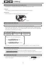
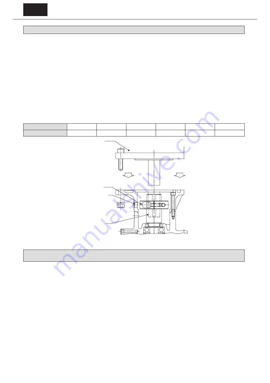
Motor
Clamp ring
Cap
High speed shaft
Figure 4-2 Assembly Diagram
4-6 Keyed Shaft Motor Assembly Issues (Hollow Connection High Speed Shaft for Servo Motor or
General Flange Motors)
[1] Remove oil, dirt, and other contaminants from the motor shaft and inside of the CYCLO Drive high speed shaft. (The inner surface of
the high speed shaft is treated with rust prevention oil before shipping.)
[2] Align the motor shaft key with the high speed hollow shaft keyway. (Keyway dimensions conform to JIS B 1301-1996 (ISO) “Keys and
Their Corresponding Keyways: Parallel keys (Normal Type)”).
[3] Coat the motor shaft with molybdenum disulfide grease to prevent fretting.
[4] Depending on the motor combination, a spacer for preventing the key from falling out may be in a separate shipment. Before
assembly, insert the spacer deep into the hole in the high speed shaft. Operation with uninserted spacer could result in the key
falling out and damaging the shaft.
[5] When assembling the motor and CYCLO Drive, make sure that the centers of both shafts are aligned. Do not force the assembly if the
shafts are slanted or misaligned or if the key is only partially engaged.
[6] Fasten the motor and adapter plate (internal cover) using the motor mounting bolt. Tighten after confirming that the motor fitting
is securely inserted into the adapter plate (internal cover) fitting. Important: If the bolt is tightened when the fitting is not inserted,
uneven tightening will result, causing damage to the internal bearing and other components.


