


16
6. Wiring
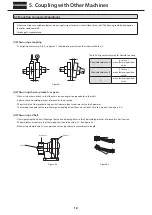
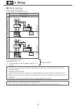
6-1 Removing and Attaching the Resin Terminal Box Cover
3-phase motor 4P: 0.1–0.4kW, high-efficiency, 3-phase motor 4P: 0.2kW, AF motor for inverter: 0.1–0.2kW
(1) Removal
As shown in figure 6-1, to remove the cover, grab the sides of the terminal box, and pull it toward you.
(2) Attachment
Push the terminal box cover from above the terminal box case until a click is heard.
Figure 6-1
6-2 Measuring Insulation Resistance
When measuring insulation resistance, always disconnect the control board and measure the motor alone.
Measure insulation resistance before wiring. Insulation resistance (R) is changed by a number of factors, including motor output,
voltage, type of insulation, winding temperature, moisture, degree of fouling, time used, and amount of time test voltage is applied.
However, normally, it must be above the values in Table 6-1.
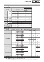
Table 6-1 Values for Insulation Resistance
Motor voltage
Megaohmmeter voltage
Insulation resistance (R)
Low-voltage electric motors of
no more than 600V
500V
Minimum 1 MΩ
Reference: JEC -2100 contains the following equation.
Rated Voltage (V) + (RPM/3)
R
≧
+ 0.5 (MΩ)
Rated output power (kW) + 2,000
Rated Voltage (V)
R
≧
(MΩ)
Rated output power (kW) + 1,000
Low insulation resistance is a sign that there is an insulation failure. Do not apply power. Consult an accredited service station.
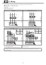
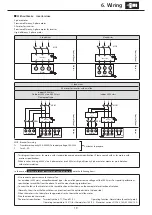
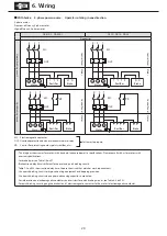
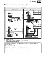
6-3 Coordination of System Protection
- Use a wiring breaker for short circuit proofing.
- Use an overload protection device designed to handle currents that exceed the rated current on the nameplate.
- For
Increased safety, explosion proof motor
, use an overload protection device capable of protecting the locked rotor current on the
nameplate within the allowable locking time.
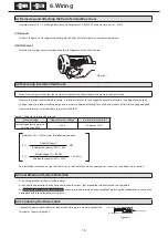
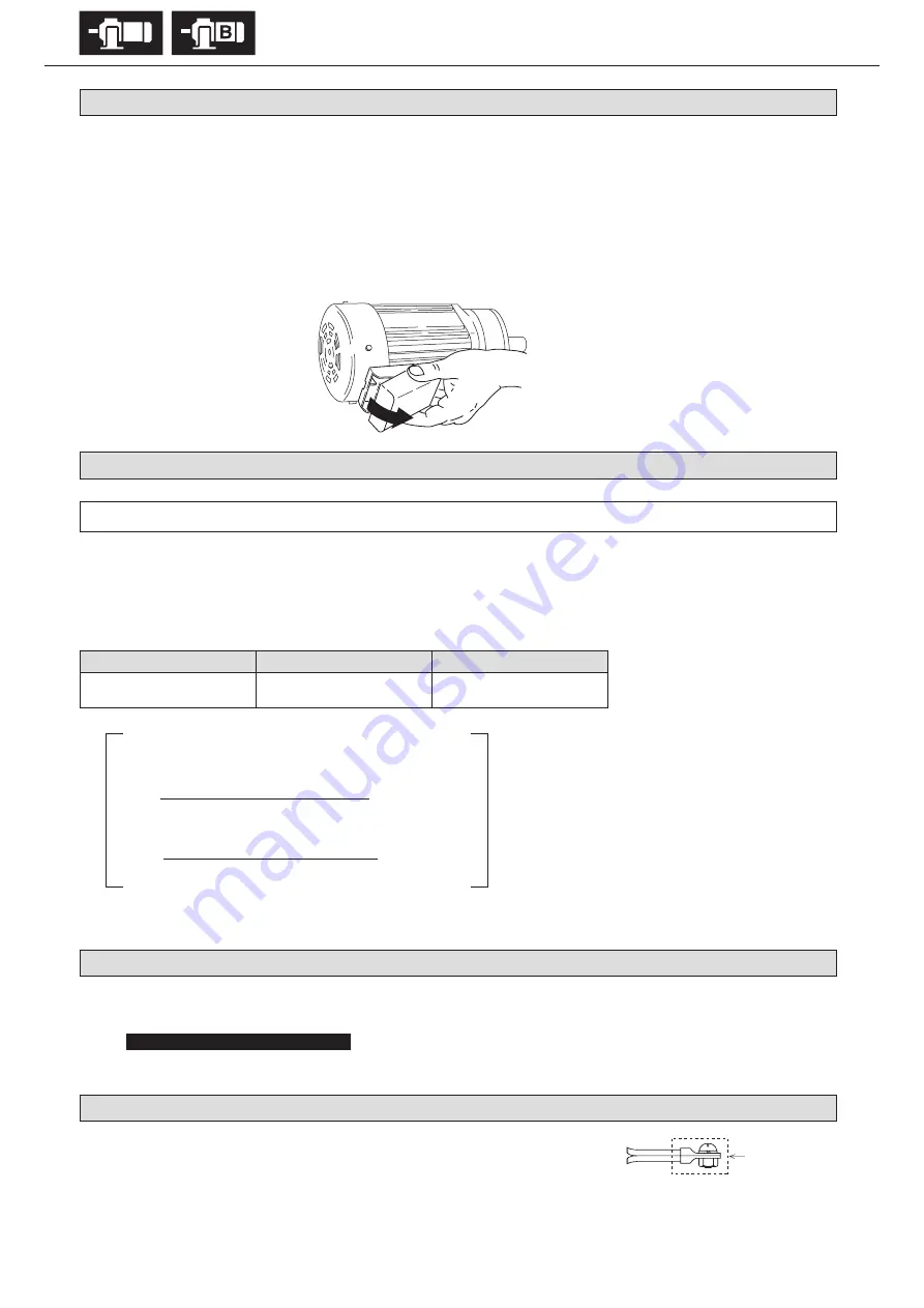
6-4 Connecting the Power Cable
Connect the power cable and motor lead wire by clasping in a pressure connection
terminal as shown in figure 6-2.
Figure 6-2
Power source cable
Motor lead wire
Insulating tape
Fig. 11


