17
16
6. Wiring
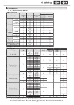
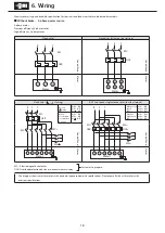
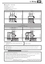
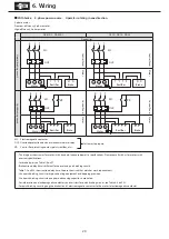
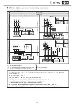
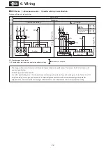
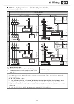
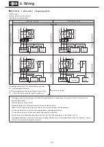
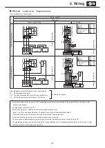
6-5 Motor Wiring
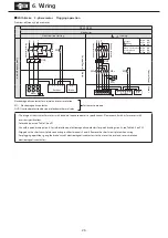
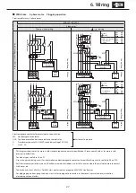
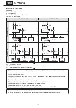
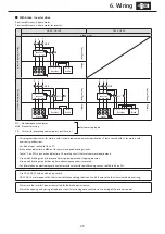
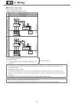
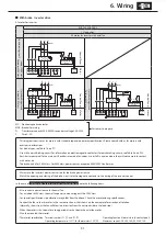
Shows the pages for motor wiring diagrams.
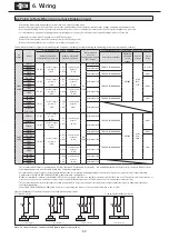
Table 6-2 Without Brake
Motor type
Number of
poles
Capacity (kW) Number of lead
wires
Page
Direct
input from
commercial
power source
Inverter drive
3-phase motor
Standard
4P
0.1–0.55
3
P18
P19
4/8P
All
6
P18
-
Increased
safety,
explosion proof
4P
0.1–7.5
11–55
3
6
P18
-
6P
7.5
11–55
3
6
P18
-
Flameproof
4P
0.1–22
30–37
3
6
P18
-
4P
0.75-3.7
5.5-55
3
6
P18
-
Premium-
efficiency,
3-phase motor
Standard
4P
0.75–3.7
5.5–55
3
6
P18
P19
6P
15-55
6
P18
P19
Increased
safety,
explosion proof
4P
0.75-3.7
5.5-11
3
6
P18
-
AF motor for
inverter
Standard
4P
0.1–0.4
30–45
3
11
-
P19
6P
18.5–45
11
-
P19
Flameproof
4P
0.2–15
22
30-55
3
6
11
-
P19
Premium-efficiency, 3-phase
motor for inverter
4P
0.75–3.7
5.5–55
3
6
-
P19
High-efficiency, 3-phase motor
4P
0.2–0.4
3
P18
P19
Table 6-3 With Brake
Motor type
Number of
poles
Capacity (kW)
Brakes
Number of lead
wires
Page
One-direction
rotation
Plugging
rotation
Inverter drive
3-phase motor
4P
0.1
FB-01A1
5
P20
P24
P28
0.2 0.25
FB-02A1
0.4
FB-05A1
0.55
FB-1D
Premium-efficiency,
3-phase motor
4P
0.75
FB-1E
5
P20
P24
P28
1.1
FB-1HE
1.5
FB-2E
2.2
FB-3E
3.0
FB-4E
3.7
FB-5E
5.5
FB-8E
8
P21
P25
P29
7.5
FB-10E
11
FB-15E
15
FB-20
P22
P26
18.5 22 30
FB-30
37 45
ESB-250
ESB-250-2
P23
P27
P30
6P
15 18.5 22
FB-30
8
P22
P23
P26
P27
P29
P30
30 37
ESB-250
ESB-250-2
AF motor for inverter
4P
0.1
FB-02A1
5
-
-
P28
0.2
FB-05A1
0.4
FB-1D
30 37
ESB-250
ESB-250-2
13
P31
6P
18.5 22 30
ESB-250
ESB-250-2
13
P31
Premium-efficiency,
3-phase motor for inverter
4P
0.75
FB-1E
5
-
-
P28
1.5
FB-2E
2.2
FB-3E
3.7
FB-5E
5.5
FB-8E
8
P29
7.5
FB-10E
11
FB-15E
15
FB-20
18.5 22 30
FB-30
37 45
ESB-250
ESB-250-2
P30
High-efficiency,
3-phase motor
4P
0.2
FB-05A1
5
P20
P24
P28
0.4
FB-1D
Note : 1. Brake type may differ depending on specification. Check the nameplate.
2. For motors with standard Japanese domestic specifications. Please consult with us for motors with overseas specifications.


