32
6. Wiring
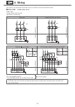
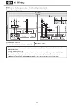
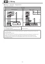
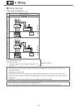
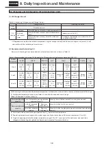
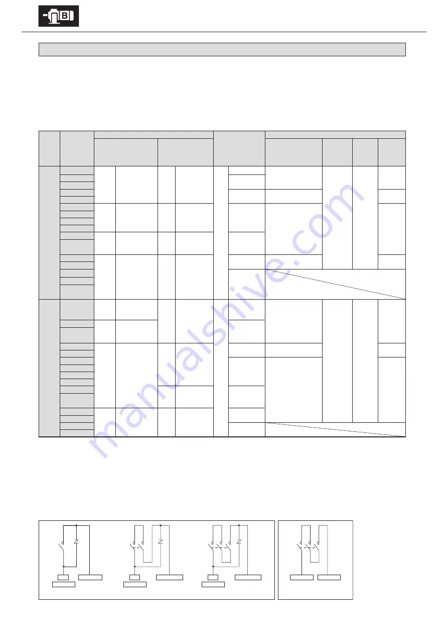
6-6 Points to Note When Using a Quick Braking Circuit
When using brakes with quick braking circuits, take note of the following items.
- Connect a varistor (protection element) to protect the quick braking circuit contact points from surge voltage generated by the brake action.
- Wire the quick braking circuit contact points to the brake power source secondary side contact points. Contact points might not be protected.
- For information on using an alternating current electromagnetic contactor for contact points for quick braking circuits, see Table 6-4.
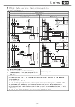
If multiple contact points are required, note the following issues.
- Connect electromagnetic contactor contact points in serial. (See figure 6-3)
- Connect the varistor (VR) as close to the unit as possible. (See figure 6-3)
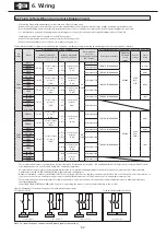
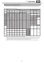
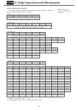
Table 6-4 Nomenclature for parts recommended when using a quick braking circuit (when using an alternating current electromagnetic contactor).
AC
voltage
Brakes
Recommended contactor nomenclature
Recommended
contactor
Contact point capacity
(DC-13 class)
Recommended varistor (for protecting contactor contact points)
Made by Fuji Electric FA
Components & Systems Co., Ltd.
Made by Mitsubishi
Electric Corporation
Varistor nomenclature
Maximum
allowable
circuit
voltage
Varistor
voltage
Power
rating
200V
220V
FB-01A1
SC-05
Serial contact
points: 1
(0.7A)
S-N11
or
S-N12
Serial contact
points: 1
(1.2A)
DC
110V
Minimum 0.4A
TND07V-471KB00AAA0
AC300V
470V
(423–
517V)
0.25 W
FB-02A1
Minimum 0.5A
FB-05A1
FB-1D
Minimum 0.7A TND10V-471KB00AAA0
0.4 W
FB-1E
FB-1HE
SC-05
Serial contact
points: 2
(3.0A)
S-N11
or
S-N12
Serial contact
points: 2
(3.0A)
Minimum 1.5A
TND14V-471KB00AAA0
0.6 W
FB-2E
FB-3E
FB-4E
FB-5E
SC-05
Serial contact
points: 3
(4.0A)
S-N18
Serial contact
points: 3
(5.0A)
Minimum 3.0A
FB-8E
FB-10E
SC-5-1
Serial contact
points: 3
(10A)
S-N20
or
S-N21
Serial contact
points: 3
(10A)
Minimum 5.5A TND20V-471KB00AAA0
1.0 W
FB-15E
FB-20
Minimum 4.5A
FB-30
ESB-250
ESB-250-2
400V
440V
FB-01A1
SC-05
Serial contact
points: 1
(0.25A)
S-N11
or
S-N12
Serial contact
points: 2
(0.5A)
DC
220V
Minimum 0.2A
TND10V-821KB00AAA0
AC510V
820V
(738–
902V)
0.4 W
FB-02A1
SC-05
Serial contact
points: 2
(0.4A)
Minimum 0.3A
FB-05A1
FB-1D
SC-05
Serial contact
points: 3
(2.0A)
S-N11
or
S-N12
Serial contact
points: 3
(2.0A)
Minimum 0.5A TND14V-821KB00AAA0
0.6 W
FB-1E
FB-1HE
Minimum 1.0A
TND20V-821KB00AAA0
1.0 W
FB-2E
FB-3E
FB-4E
FB-5E
S-N18
Serial contact
points: 3
(2.0A)
Minimum 1.5A
FB-8E
FB-10E
-
-
S-N20
or
S-N21
Serial contact
points: 3
(4.0A)
Minimum 3.0A
FB-15E
FB-20
Minimum 2.5A
FB-30
- This recommended contactor nomenclature is for Fuji Electric FA Components & Systems Co., Ltd. and Mitsubishi Electric Corporation contactors. Products from
other manufacturers are also allowable if they have equivalent capabilities.
- Recommended contactor contact point capacity indicates the case where durability regarding electronic opening and closing (service life) is approximately
2 million times (for FB-30, ESB-250 and ESB-250-2, approximately 1 million times).
- Of the recommended contactors, the Mitsubishi Electric Corporation S-N11 has one auxiliary contact point; the S-N18 has none. This applies if, for inverter drive or
other reasons, two or more auxiliary contact points are required. (Other connectors in Table 6-4 have two or more auxiliary contact points.)
- This recommended varistor nomenclature is for Nippon Chemi-Con Corporation varistors. Products from other manufacturers are also allowable if they have
equivalent capabilities.
- In the FB-20, FB-30, ESB-250 and ESB-250-2, a varistor for protecting the connector contact points is built in to the rectifier.
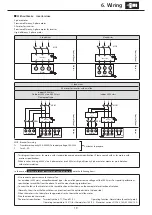
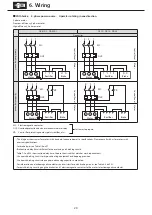
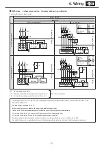
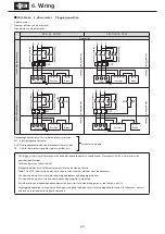
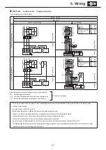
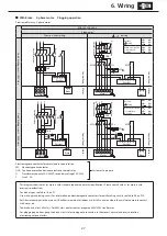
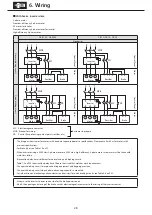
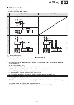
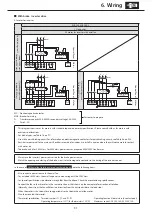
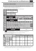
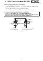
Figure 6-3 Examples of contact point connections with quick braking circuits
VR
Brake terminal
N
U
phase
MC
Rectifier terminal 5
Rectifier terminal 5
Rectifier terminal 2
Rectifier terminal 2
Rectifier terminal 2
MC
VR
Brake terminal
N
U
phase
MC
Serial contacts: 1
For FB-01A1
–
FB-15E
For FB-20, FB-30, ESB-250 and ESB-250-2
Serial contacts: 2
Serial contacts: 3
Serial contacts: 3
MC
VR
Brake terminal
N
U
phase
Note
Note
Note
Note : For inverter drives, connect to the R phase (power source side).


