33
33
6. Wiring
6-7 Wiring for Motorized Trochoid Pump Motor
CAUTION
- When lubricating with a motorized trochoid pump, always prime before starting the main motor. Abnormal temperature
rise, seizure, and other device damage may occur.
(1)
Vertical frame sizes 6275, 6275DA
Use a trochoid pump for independent lubrication. The pump requires a separate power source.
(See Table 6-5, figure 6-4)
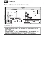
(2) For motorized trochoid pump wiring, see figure 6-5. Wire R-U, S-V, T-W. The pump motor rotates in the specified direction. (For
Japanese domestic standard specifications. Consult with us for special specification, such as overseas specifications and motors not
manufactured by Sumitomo.)
(3) Between the motor for the motorized trochoid pump and main motor, fit with interlock that satisfies the following two functions. (See
figure 6-5)
[1] Start time: If the motorized trochoid pump does not activate, do not activate the main motor.
[2] While running: If for any reason the motorized trochoid pump stops, stop the main motor.
(4) To ensure good lubricating conditions, start (prime) the motorized trochoid pump at least 30 seconds before the main motor.
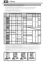
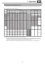
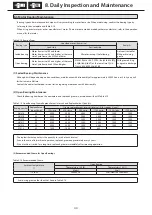
Table 6-5 Motorized Trochoid Pump Specifications
Type
Motorized trochoid pump
Remarks
Frame size
Reduction
ratio
Pump
nomenclature
Pump motor
50 Hz region
60 Hz region
(1) Motorized trochoid pumps manufactured
by Nippon Oil Pump Co., Ltd. are used as
standard equipment.
(2) The motorized trochoid pump comes
standard with a release valve (set pressure
0.29 MPa).
Discharge
volume
(L/min)
Maximum
pressure
(MPa)
Discharge
volume
(L/min)
Maximum
pressure
(MPa)
Ver
tical
6275
Total
reduction
ratio
TOP-216HB-
VB-3
0.75kW 4P
24.0
0.78
28.8
0.49
6275DA
Total
reduction
ratio
TOP-204HB-
VB-3
0.4kW 4P
6.0
1.57
7.2
1.13
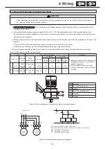
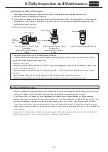
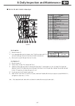
Figure 6-4 Structural diagram of machine with motorized trochoid pump
メインモータ
電動トロコイド
ポンプ用
モータ
OLR
OLR
MC2
MC1
R
S
電源
T
R1
PB2
S1
PB1
MC2
T
T
MC1
MC2
a
b
c
d
e
f
M
a Flow sight
b Motorized trochoid pump
c Coupling
d Motor (for trochoid pump)
e Filler plug
f Oil gauge
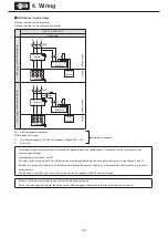
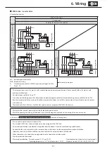
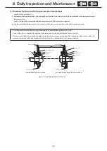
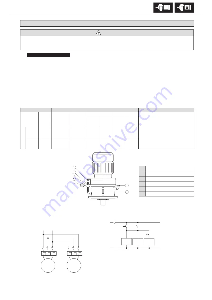
Figure 6-5 Motorized trochoid pump circuit diagram
R
S
T
Power source
MC1
Main
Motor
Motor for
motorized
trochoid
pump
MC2
E
E
MC2
MC1
T
R1
S1
MC1: Electromagnetic contactor (Main motor)
MC2: Electromagnetic contactor (Motor for motorized trochoid pump)
PB1: Push button switch (Start)
PB2: Push button switch (Stop)
T: Timer (30 or more seconds)
T
PB2
PB1
MC2
OLR
OLR


