
57
56
8. Daily Inspection and Maintenance
-
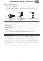
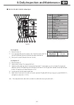
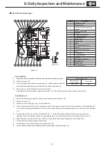
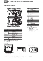
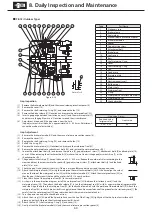
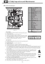
Gap Inspection
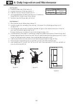
(1) Remove cover [8].
(2) Insert a gap gauge between the field [4] and armature [12] and measure the
gap. Measure in 4 locations around the circumference.
(3) Adjustment is required if the gap value is near the limit.
-
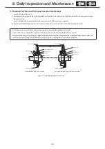
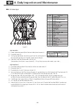
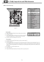
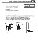
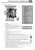
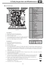
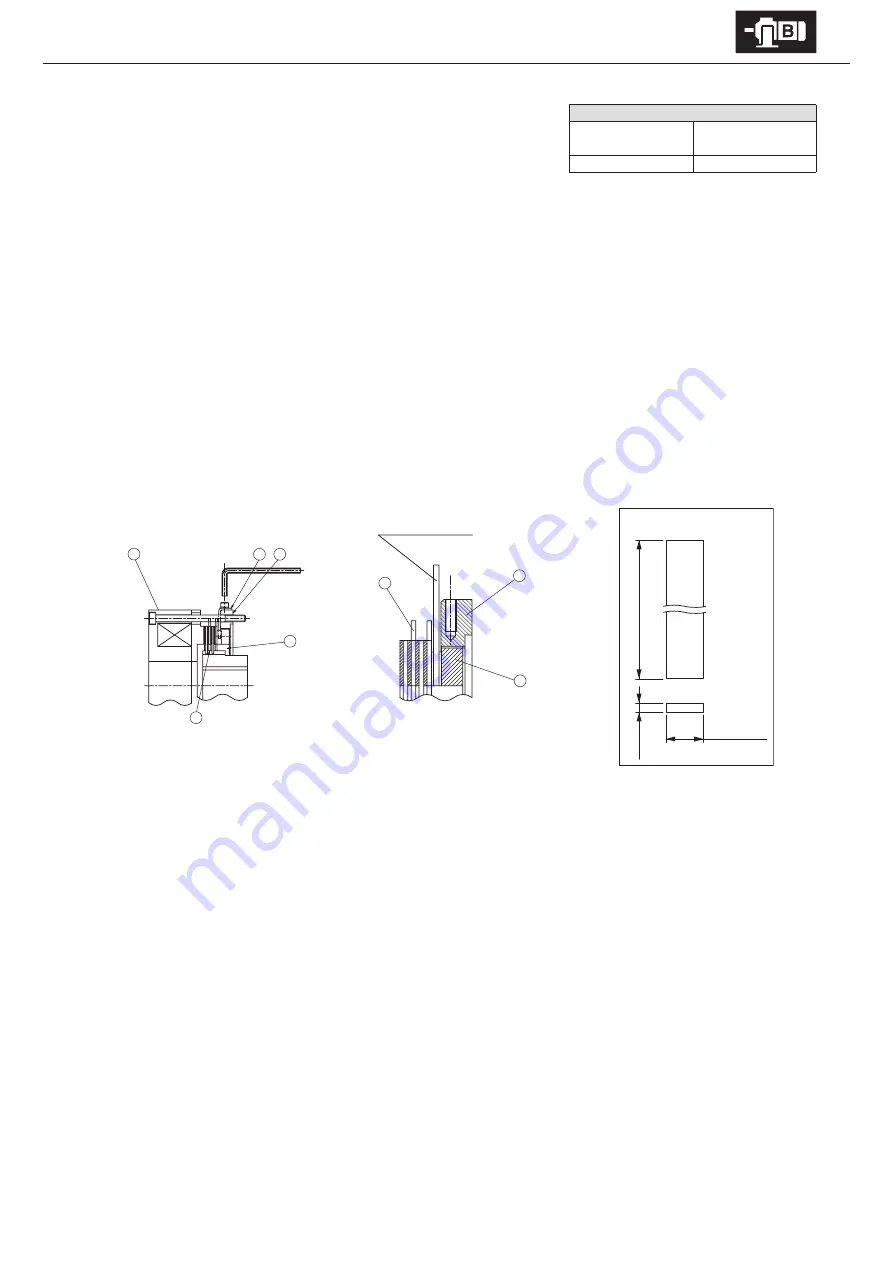
Gap Adjustment
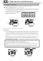
(1) Manually release the brake following the procedure on P71.
(2) Loosen the stopper [16] on the periphery of the center ring [1], and remove it. This will free the gap adjusting screws [2].
(See Figure 8-19)
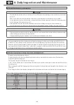
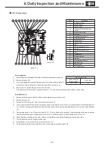
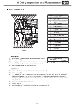
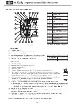
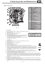
(3) Insert the gap adjusting bar (customer to prepare an angle plate. See Figure 8-21) from between the outer disc [14] and the
center ring [1] into a hole for a gap adjusting screw [2].
Rotating to the left as seen from the field [4] side, will narrow the gap. (See Figure 8-20)
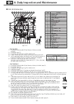
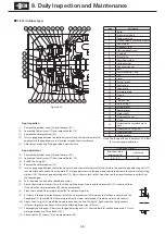
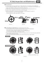
(4) Six attachment bolts [3] and 6 lock bolts [11] alternately pass through the space between the outer disc [14] and the center ring
[1]. Rotating the gap adjusting bar will contact these bolts. There are 8 equally distributed holes for gap adjusting screws [2].
Adjust the gap G to the required value by repeating (3) each time the gap adjusting bar contacts a bolt,.
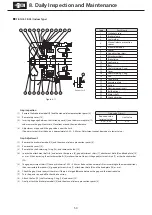
(5) Select the point where hole and screw hole are closest to the required gap and attach the stopper [16] there.
(6) After returning the manual brake release to its original state, turn power on and off to check brake action.
(7) Attach the fan [7] and cover [8]. At this time coat the fan set screw [10] with Three Bond TB2365.
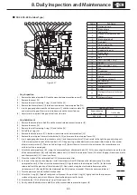
4
16
1
2
14
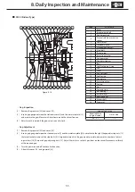
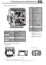
Gap adjusting bar
2
1
14
Gap adjusting
bar dimensions
14.7 ± 0.1 mm
150m
m
3.5 mm
Figure 8-19
Figure 8-20
Figure 8-21
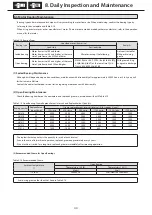
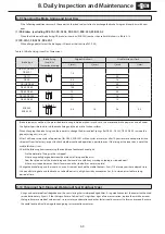
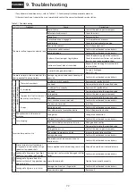
Gap value G (mm)
Required value
(original value)
Limit value
0.7
2.0


