
71
70
8. Daily Inspection and Maintenance
■
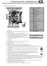
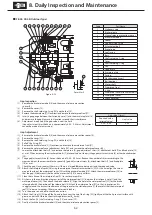
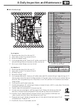
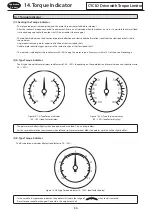
ESB-250, ESB-250-2
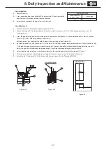
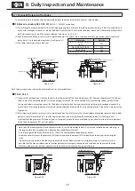
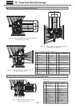
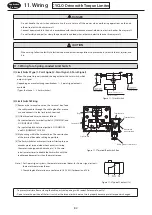
(1) In the case of outdoor types, remove outdoor cover [25]. Remove the cover [8], fan [7], and brake cover [22] (outdoor type).
(2) Insert M12×65 hexagon socket head bolts (customer to prepare) through the manual releasing holes, to the field. (Note that if the
hexagon socket head bolts are too long they will hit the outer disc and deform it.)
(3) There are two manual release holes at opposing angles. Using a hexagonal wrench equally tighten the bolts in turn.
(4) To release the brake, tighten the bolts until the armature and field stick together.
(5) After returning the brake to its original state, attach the brake cover [22] (outdoor type), fan [7], and cover [8].
At this time coat the fan set screw [10] with Three Bond TB2365.
In the case of outdoor types, attach the outdoor cover as it was before.
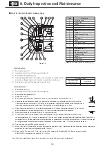
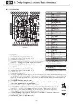
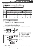
Brake release
hole
Brake release
hole
Inner disc
Outer disc
Armature
Field
Hexagon socket
head bolt
Gap
Adheres Hexagonal wrench
Figure 8-40
Figure 8-41
Figure 8-42
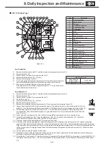
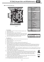
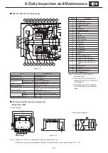
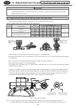
■
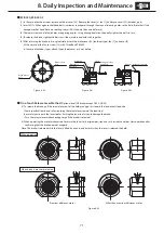
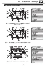
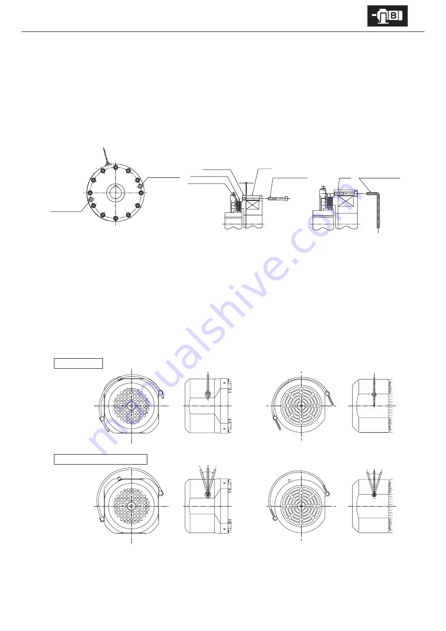
One-Touch Release Lever Method
(Optional on all FB brakes except FB-20, FB-30)
(1) To release the brake, pull the release lever out of the holder, and push it toward the load or anti-load side.
(Some specifications do not allow pushing the release lever toward the load side.)
Be careful not to push the lever too far. Pushing the lever too far could damage the brake.
(Push the release lever while checking to see if the brake is released.)
(2) When operating the motor make certain to return the lever to its original position and set it inside the holder. Start operation after
confirming that the brake operates properly.
Note : The brake is released while the lever is tilted by a hand, and it works when the lever is released the hold.
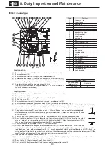
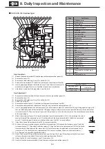
Figure 8-43
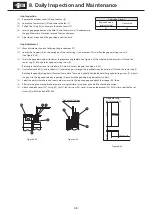
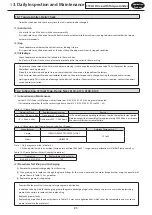
When brake is manually released
Premium efficiency motor
Other than premium efficiency motor
When operating


