
76
10. Construction Drawings
Common
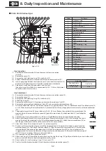
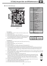
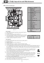
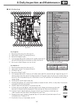
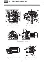
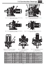
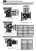
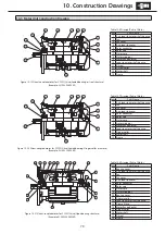
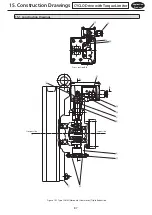
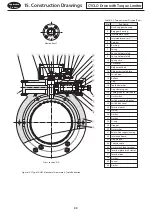
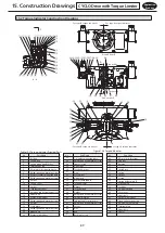
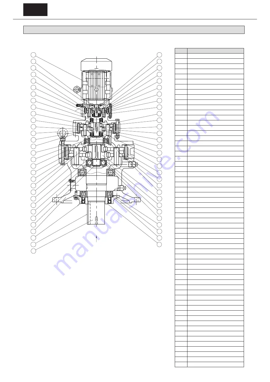
10-2 Gear Unit Construction Drawings (Triple Reduction)
Table10-2 Gear Unit, Principal Parts
(Triple Reduction)
Code
Part Name
1
Slow speed shaft (Output shaft)
2
Key
3
Oil seal
4
Flanged casing
5
Intermediate shaft
6
Ball bearing
7
Key
8
Roller bearing
9
Slow speed shaft pin
10
Spacer ring
11
Slow speed shaft roller
12
Gasket B
13
Spacer ring
14
Ball bearing
15
Intermediate shaft
16
Gasket C
17
Gasket B
18
Key
19
Ring gear pin
20
Ring gear roller
21
Spacer ring
22
Gasket C
23
Spacer ring
24
Ball bearing
25
Gasket B.C
26
Ring gear roller
27
Grease fitting (with cap)
28
Ring gear pin
29
Eccentric cam
30
Spacer ring
31
Motor
32
Slinger
33
Key
34
Slow speed shaft pin
35
Slow speed shaft roller
36
Cycloid disc
37
Spacer ring
38
Ring gear housing
39
Spacer ring
40
Ball bearing
41
Intermediate cover
42
Slow speed shaft roller
43
Cycloid disc
44
Ring gear housing
45
Slow speed shaft pin
46
Eccentric cam
47
Intermediate cover
48
Spacer ring
49
Ring gear housing
50
Ring gear roller
51
Ring gear pin
52
Cycloid disc
53
Ball bearing
54
Eccentric
55
End plate
56
Ball bearing
57
Spacer ring
58
Gasket A
59
Gland
60
Ball bearing
61
Collar
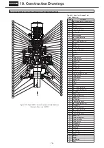
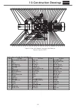
Figure 10-13 Type CVVM (Vertical, Gearmotor), Triple Reduction
(Example: Frame size 6185TD)
1
2
3
4
5
6
7
8
9
10
11
12
13
14
15
16
18
17
19
20
21
22
23
24
25
26
27
28
29
30
31
32
33
34
35
36
37
38
39
40
41
42
43
44
45
46
47
48
49
50
51
52
53
54
55
56
57
58
59
60
61
A


