background image

66

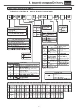
1. Inspection upon Delivery

Common

Table 1-1 SK Series Frame Sizes

Frame size

6070SK

6080SK

6090SK

6100SK

6110SK

6075SK

6085SK

6095SK

6105SK

6115SK

Table 1-2 Low Reduction Ratio Series Frame Sizes

Frame size

6130

6140

6160

6170

6135

6145

6165

6175

Table 1-3 Single Reduction Frame Sizes

Frame size

6060

6065

6090

6095

6110

6115

6130

6135

6160

6165

616H

6180

6185

6205

6235

6265

6070

6075

6100

6105

610H

6120

6125

612H

6140

6145

614H

6190

6195

6215

6245

6275

6080

6085

6170

6175

6225

6255

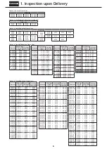
Table 1-4 Double Reduction Frame Sizes

Frame size

Second stage

(Output 

stage)

First stage

(Input stage)

Frame size

Second stage

(Output 

stage)

First stage

(Input stage)

Frame size

Second stage

(Output 

stage)

First stage

(Input stage)

Frame size

Second stage

(Output 

stage)

First stage

(Input stage)

6060DA

6060 

 6060

6130DA

6130 

 6075

6165DA

6165 

 6095

6205DA

6205 

 6125

6065DA

6065 

 6065

6130DB

6130 

 6095

6165DB

6165 

 6105

6205DB

6205 

 6135

6070DA

6070 

 6065

6130DC

6130 

 6105

6165DC

6165 

 6125

6215DA

6215 

 6135

6075DA

6075 

 6065

6135DA

6135 

 6075

6170DA

6170 

 6095

6215DB

6215 

 6165

6090DA

6090 

 6075

6135DB

6135 

 6095

6170DB

6170 

 6105

6225DA

6225 

 6135

6095DA

6095 

 6075

6135DC

6135 

 6105

6170DC

6170 

 6125

6225DB

6225 

 6175

6100DA

6100 

 6075

6140DA

6140 

 6075

6175DA

6175 

 6095

6235DA

6235 

 6165

6105DA

6105 

 6075

6140DB

6140 

 6095

6175DB

6175 

 6105

6235DB

6235 

 6185

6120DA

6120 

 6075

6140DC

6140 

 6105

6175DC

6175 

 6125

6245DA

6245 

 6165

6120DB

6120 

 6095

6145DA

6145 

 6075

6180DA

6180 

 6105

6245DB

6245 

 6185

6125DA

6125 

 6075

6145DB

6145 

 6095

6180DB

6180 

 6135

6255DA

6255 

 6175

6125DB

6125 

 6095

6145DC

6145 

 6105

6185DA

6185 

 6105

6255DB

6255 

 6195

6160DA

6160 

 6095

6185DB

6185 

 6135

6265DA

6265 

 6195

6160DB

6160 

 6105

6190DA

6190 

 6125

6275DA

6275 

 6195

6160DC

6160 

 6125

6190DB

6190 

 6135


6195DA

6195 

 6125


6195DB

6195 

 6135

Table 1-5 Triple Reduction Frame Sizes

Frame size

Third stage

(Output 

stage)

Second stage

(Intermediate 

stage)

First stage

(Input stage)

Frame size

Third stage

(Output 

stage)

Second stage

(Intermediate 

stage)

First stage

(Input stage)

Frame size

Third stage

(Output 

stage)

Second stage

(Intermediate 

stage)

First stage

(Input stage)

6060TA  6060 + 6060  + 6060 

6170TA    6170 + 6095  +  6075

6205TA    6205 +  6125  + 6075 

6065TA  6065 + 6065  + 6065 

6170TB    6170 + 6105  +  6075

6205TB    6205 +  6125  + 6095 

6070TA  6070 + 6065  + 6065 

6170TC    6170 + 6125  +  6075

6205TC    6205 +  6135  + 6075 

6075TA  6075 + 6065  + 6065 

6170TD    6170 + 6125  +  6095

6205TD    6205 +  6135  + 6095 

6090TA  6090 + 6075  + 6065 

6175TA    6175 + 6095  +  6075

6205TE    6205 +  6135  + 6105 

6095TA  6095 + 6075  + 6065 

6175TB    6175 + 6105  +  6075

6215TA    6215 +  6135  + 6075 

6100TA  6100 + 6075  + 6065 

6175TC    6175 + 6125  +  6075

6215TB    6215 +  6135  + 6095 

6105TA  6105 + 6075  + 6065 

6175TD    6175 + 6125  +  6095

6215TC    6215 +  6135  + 6105 

6120TA  6120 + 6075  + 6065 

6180TA    6180 + 6105  +  6075

6215TD    6215 +  6165  + 6095 

6120TB  6120 + 6095  + 6075 

6180TB    6180 + 6135  +  6075

6215TE    6215 +  6165  + 6105 

6125TA  6125 + 6075  + 6065 

6180TC    6180 + 6135  +  6095

6215TF    6215 +  6165  + 6125 

6125TB  6125 + 6095  + 6075 

6180TD    6180 + 6135  +  6105

6225TA    6225 +  6135  + 6075 

6130TA  6130 + 6075  + 6065 

6185TA    6185 + 6105  +  6075

6225TB    6225 +  6135  + 6095 

6130TB  6130 + 6095  + 6075 

6185TB    6185 + 6135  +  6075

6225TC    6225 +  6135  + 6105 

6130TC  6130 + 6105  + 6075 

6185TC    6185 + 6135  +  6095

6225TD    6225 +  6175  + 6095 

6135TA  6135 + 6075  + 6065 

6185TD    6185 + 6135  +  6105

6225TE    6225 +  6175  + 6105 

6135TB  6135 + 6095  + 6075 

6190TA    6190 + 6125  +  6075

6225TF    6225 +  6175  + 6125 

6135TC  6135 + 6105  + 6075 

6190TB    6190 + 6125  +  6095

6235TA    6235 +  6165  + 6095 

6140TA  6140 + 6075  + 6065 

6190TC    6190 + 6135  +  6075

6235TB    6235 +  6165  + 6105 

6140TB  6140 + 6095  + 6075 

6190TD    6190 + 6135  +  6095

6235TC    6235 +  6165  + 6125 

6140TC  6140 + 6105  + 6075 

6190TE    6190 + 6135  +  6105

6235TD    6235 +  6185  + 6105 

6145TA  6145 + 6075  + 6065 

6195TA    6195 + 6125  +  6075

6235TE    6235 +  6185  + 6135 

6145TB  6145 + 6095  + 6075 

6195TB    6195 + 6125  +  6095

6245TA    6245 +  6165  + 6095 

6145TC  6145 + 6105  + 6075 

6195TC    6195 + 6135  +  6075

6245TB    6245 +  6165  + 6105 

6160TA  6160 + 6095  + 6075 

6195TD    6195 + 6135  +  6095

6245TC    6245 +  6165  + 6125 

6160TB  6160 + 6105  + 6075 

6195TE    6195 + 6135  +  6105

6245TD    6245 +  6185  + 6105 

6160TC  6160 + 6125  + 6075 

6245TE    6245 +  6185  + 6135 

6160TD  6160 + 6125  + 6095 

6255TA    6255 +  6175  + 6095 

6165TA  6165 + 6095  + 6075 

6255TB    6255 +  6175  + 6105 

6165TB  6165 + 6105  + 6075 

6255TC    6255 +  6175  + 6125 

6165TC  6165 + 6125  + 6075 

6255TD    6255 +  6195  + 6125 

6165TD  6165 + 6125  + 6095 

6255TE    6255 +  6195  + 6135 

6265TA    6265 +  6195  + 6125 

6265TB    6265 +  6195  + 6135 

6275TA    6275 +  6195  + 6125 

6275TB    6275 +  6195  + 6135 

Summary of Contents for CYCLO

Page 1: ...aintenance manual before use A copy of this maintenance manual should be sent to the actual user This maintenance manual should be kept by the user for future reference CYCLO Drive Gearmotor Reducer C...

Page 2: ......

Page 3: ...rformed by trained technicians otherwise electric shock injury fire or damage to the equipment may result In the case of maintenance with disassembly please contact the nearest authorized service stat...

Page 4: ...ion product Without brake With brake Mark Contents Common Introduction Safety Precautions 1 Introduction How to Refer to the Maintenance Manual Table of Contents 2 1 Inspection Upon Delivery 3 2 Stora...

Page 5: ...UT TORQUE SERVICE FACTOR MODEL VOLTS kW P TYPE FRAME TIME RATING M B INS CLASS JISC4004 B TORQUE N m N m N m Hz M AMP r min B AMP SERIAL NO R R J A P A N 1 Gearmotor nomenclature See P5 2 Reduction ra...

Page 6: ...1 2 Gear unit nameplate Confirm that the preset torque value marked in the gear unit nameplate and the preset torque value marked on the adjustment indicator plate see P84 are the same as the required...

Page 7: ...ange V V Flange Model symbol C CYCLO Drive CYCLO Drive SK series P CYCLO Drive low reduction ratio series Special specification Blank Standard specifica tion S Special specifica tion With or without b...

Page 8: ...Input stage Frame size Third stage Output stage Second stage Intermediate stage First stage Input stage 6060TA 6060 6060 6060 6170TA 6170 6095 6075 6205TA 6205 6125 6075 6065TA 6065 6065 6065 6170TB 6...

Page 9: ...Increased safety explosion proof indoor type B Increased safety explosion proof out door type C Indoor flameproof CX Outdoor flameproof X Outdoor honexplosion proof Blank Indoor honexplosion proof 1 5...

Page 10: ...ns Store in an ordinary factory or warehouse in an environment free of moisture dust extreme temperature changes corrosive gases etc If for export or if the storage time is longer than one year adhere...

Page 11: ...equipment and or lifting device may result Before hoisting refer to the rating plate crate outline drawing catalog etc for the weight of the unit Never hoist a unit that exceeds the rating of the cra...

Page 12: ...device to cope with oil leakage due to breakdown or failure otherwise oil leakage may damage products Always drain oil lubricated models before mounting moving and transporting Moving with lubricatin...

Page 13: ...ts with the nut for ring gear housing removed does not generate a sufficient level of torque Do not use only the disassembly prevention nuts for ring gear housing for long periods of time move them ex...

Page 14: ...or the clamp ring hexagon socket head bolt Bolt size M4 M5 M6 M8 M10 M12 Tightening Torque N m 4 3 5 5 9 6 23 46 79 Motor Clamp ring Cap High speed shaft Figure 4 2 Assembly Diagram 4 6 Keyed Shaft Mo...

Page 15: ...the broken pieces or of damage to the products 5 1 Checking Rotational Direction 1 For gearmotor Table 5 1 shows the direction of slow speed shaft rotation when wiring is performed as on P18 31 Table...

Page 16: ...the sprocket and gear shall be more than three times of the shaft diameter The working load point of the sprocket or gear should go from the center of the shaft to this product See figure 5 2 3 When...

Page 17: ...measuring insulation resistance otherwise electric shock may result When using a When using a star delta starter select one with an electromagnetic switch on the primary side 3 contact point type oth...

Page 18: ...ble 6 1 Values for Insulation Resistance Motor voltage Megaohmmeter voltage Insulation resistance R Low voltage electric motors of no more than 600V 500V Minimum 1 M Reference JEC 2100 contains the fo...

Page 19: ...ty kW Brakes Number of lead wires Page One direction rotation Plugging rotation Inverter drive 3 phase motor 4P 0 1 FB 01A1 5 P20 P24 P28 0 2 0 25 FB 02A1 0 4 FB 05A1 0 55 FB 1D Premium efficiency 3 p...

Page 20: ...OFF MC ON When acceleration is completed wiring MCM ON MC ON MC OFF When at low speed 8P MCL ON MCH1 OFF MCH2 OFF When at high speed 4P MCL OFF MCH1 ON MCH2 ON Control Panel Control Panel Motor Motor...

Page 21: ...e the following items Also connect a power source to the axial fan For an indoor 400V class except flameproof type the axial fan power source voltage will be 200V class For special specifications spec...

Page 22: ...rseas specifications For brake types see Table 1 6 on P7 Brake action delay time is different for normal and quick braking circuits Table 7 2 on P35 shows action delay time Choose the circuit that mat...

Page 23: ...overseas specifications For brake types see Table 1 6 on P7 Brake action delay time is different for normal and quick braking circuits Table 7 2 on P35 shows action delay time Choose the circuit that...

Page 24: ...apanese domestic specifications Please consult with us for motors with overseas specifications For brake types see Table 1 6 on P7 Use with a quick braking circuit For information on electromagnetic c...

Page 25: ...lt with us for motors with overseas specifications For brake types see Table 1 6 on P7 Use with a quick braking circuit For information on electromagnetic contactors for quick braking circuits see Tab...

Page 26: ...y time is different for normal and quick braking circuits Table 7 2 on P35 shows action delay time Choose the circuit that matches work requirements Use a quick braking circuit to improve hoisting equ...

Page 27: ...ay time is different for normal and quick braking circuits Table 7 2 on P35 shows action delay time Choose the circuit that matches work requirements Use a quick braking circuit to improve hoisting eq...

Page 28: ...ons Please consult with us for motors with overseas specifications For brake types see Table 1 6 on P7 Use with a quick braking circuit For information on electromagnetic contactors for quick braking...

Page 29: ...rs with overseas specifications For brake types see Table 1 6 on P7 Use with a quick braking circuit For information on electromagnetic contactors for quick braking circuits see Table 6 4 on P32 Recti...

Page 30: ...measures must be taken with motor insulation Brake action delay time is different for normal and quick braking circuits Table 7 2 on P35 shows action delay time Choose the circuit that matches work r...

Page 31: ...t matches work requirements Use a quick braking circuit to improve hoisting equipment and stopping precision Use a quick braking circuit when a phase advancing capacitor is mounted For information on...

Page 32: ...able 1 6 on P7 Use with a quick braking circuit For information on electromagnetic contactors for quick braking circuits see Table 6 4 on P32 Rectifiers are external to the main unit Rectifiers are ma...

Page 33: ...brake circuit s electromagnetic contactor to the timing of the inverter control In the case of With axial fan totally enclosed ventilated types note the following items Also connect a power source to...

Page 34: ...50 2 400V 440V FB 01A1 SC 05 Serial contact points 1 0 25A S N11 or S N12 Serial contact points 2 0 5A DC 220V Minimum 0 2A TND10V 821KB00AAA0 AC510V 820V 738 902V 0 4 W FB 02A1 SC 05 Serial contact p...

Page 35: ...d trochoid pump at least 30 seconds before the main motor Table 6 5 Motorized Trochoid Pump Specifications Type Motorized trochoid pump Remarks Frame size Reduction ratio Pump nomenclature Pump motor...

Page 36: ...personal injury or damage to the equipment may result 7 1 Items to Check Before Operation After installation and wiring are completed check the following items before operating Is the wiring correct...

Page 37: ...0 35 FB 2E 1 5 1 5 15 0 35 0 55 0 15 0 25 FB 3E 2 2 2 2 22 0 75 0 95 0 4 0 5 0 02 0 04 FB 4E 3 0 30 0 65 0 85 0 3 0 4 FB 5E 3 7 3 7 40 1 1 1 3 0 4 0 5 FB 8E 5 5 5 5 55 1 0 1 2 0 3 0 4 FB 10E 7 5 7 5 8...

Page 38: ...industrial waste When measuring the insulation resistance of an For explosion proof motors confirm that there is no gas or other vaporized explosive substance around the unit in order to prevent explo...

Page 39: ...ontal Long life grease Grease Vertical Note 1 Indicates universal mounting direction 2 Indicates independent lubrication using a trochoid pump See 6 7 Wiring for Motorized Trochoid Pump Motor P33 3 Th...

Page 40: ...Gear Oil 100 150 Shell Omala S2 G 100 150 Spartan EP 150 Mobilgear 600 XP 100 150 Gulf EP Lubricant HD 100 150 Meropa 100 150 Energol GR XP 100 150 30 to 50 COSMO GEAR SE 220 460 BONNOC M 220 460 BON...

Page 41: ...18 23 32 60 Vertical 1 0 1 9 2 0 2 7 2 7 11 14 18 23 29 42 51 60 Table 8 8 Oil Fill Quantity L for Horizontal Chain Flight Sludge Collector Specification Double Reduction Frame size 613 DB 613 DC 614...

Page 42: ...ve the top red line churning heat may raise the temperature Use the lower red line of the oil gauge as a guideline for the oil level while the machine is running The oil level may drop below the botto...

Page 43: ...terval when the operating conditions are severe or the frame size is large 10 24 hours per day Once every 500 1 000 hours 2 Recommended Grease Grease used when shipped Table 8 12 Recommended Grease Gr...

Page 44: ...500 500 750 500 750 Triple Reduction 606 TA 607 TA 609 TA 610 TA 612 TA 612 TB Long life grease lubricated models Replenishment is not required 613 TA 613 TB 613 TC 614 TA 614 TB 614 TC 616 TA 616 TB...

Page 45: ...e the grease fitting with one that has a metal cap Be careful when handling the metal cap for the grease fitting as dropping it from a high place is dangerous Contact the nearest authorized service st...

Page 46: ...ately 20 000 hours or 3 to 5 years will further increase lifetime Contact the nearest authorized service station regarding maintenance with disassembly 2 Open Bearing Maintenance Check the bearing num...

Page 47: ...the bearing to overheat grease to leak and other problems Be careful Do not think that it is allowable to replenish with a large quantity to extend the replenishment interval Please maintain the mach...

Page 48: ...ater than the moment of inertia for the brakemotor However please periodically inspect the brake gap G The brake lining wears after long hours of running time mak ing it impossible for the brake to re...

Page 49: ...tment 1 Remove the cover 7 2 Loosen the fan set screw 8 and remove the fan 9 3 Slightly loosen the attachment bolts 4 and rotate the fixed plate 11 counterclockwise as far as it will go Then tighten t...

Page 50: ...se prevention spacer 3 2 Remove the cover 13 3 Remove the fan set screw 12 and remove the fan 14 4 Loosen the attachment bolts 7 and remove the spacers 5 gap adjustment shims 6 attachment bolts 7 and...

Page 51: ...Remove the brake release bolt 5 and the manual release prevention spacer 4 2 Remove the cover 13 3 Remove the shaft retaining C ring 14 and remove the fan 15 4 Loosen the attachment bolts 8 and remove...

Page 52: ...1 Remove the brake release bolt 5 and the manual release prevention spacer 4 2 Remove the cover 13 3 Remove the shaft retaining C ring 14 and remove the fan 15 4 Loosen the attachment bolts 8 and rem...

Page 53: ...1 Remove the brake release bolt 4 and the manual release prevention spacer 3 2 Remove the cover 12 3 Remove the shaft retaining C ring 13 and the fan 14 4 Loosen the attachment bolts 7 and remove the...

Page 54: ...around the circumference 4 Adjustment is required if the gap value is near the limit Gap Adjustment 1 Remove the brake release bolt 5 and the manual release prevention spacer 4 2 Remove the cover 14 3...

Page 55: ...locations around the circumference 4 Adjustment is required if the gap value is near the limit Gap Adjustment 1 Remove the brake release bolt 5 and the manual release prevention spacer 4 2 Remove the...

Page 56: ...nd cover 16 2 Insert a gap gauge between the stationary core 6 and the armature plate 12 and measure the gap Measure in 3 locations around the circumference 3 Adjustment is required if the gap value i...

Page 57: ...ture plate 12 and measure the gap Measure in 3 locations around the circumference 3 Adjustment is required if the gap value is near the limit Gap Adjustment 1 Remove the grommet 28 and cover 16 2 Inse...

Page 58: ...ous voltage DC180V for AC200V input Steady voltage DC90V for AC200V input Maximum output current DC1 8A Steady output Over excitation time 0 4 1 2 s Insulation resistance 100M or larger When measured...

Page 59: ...will narrow the gap See Figure 8 20 4 Six attachment bolts 3 and 6 lock bolts 11 alternately pass through the space between the outer disc 14 and the center ring 1 Rotating the gap adjusting bar will...

Page 60: ...check to see if the gap value is between the required value and the limit This operation will reduce the gap by 0 3 mm 7 Attach the waterproof cover 12 using the attachment bolts 13 Attach the waterpr...

Page 61: ...plate 6 as a set When removing the attachment bolts 5 make certain not to omit the gap adjustment shims 4 9 The gap adjusting shims 4 have a thickness of 0 2 0 25 mm Reduce the number of shims accord...

Page 62: ...as a set When removing the attachment bolts 8 make certain not to omit the gap adjustment shims 7 or the shock absorber 26 8 The gap adjustment shims 7 have a thickness of 0 2 0 25 mm Reduce the numb...

Page 63: ...tachment bolts 8 make certain not to omit the gap adjustment shims 7 or the shock absorber 26 8 The gap adjustment shims 7 have a thickness of 0 35 0 45 mm Reduce the number of shims according to the...

Page 64: ...nt bolts 7 and fixed plate 15 as a set When removing the attachment bolts 7 make certain not to omit the gap adjustment shims 6 or the shock absorber 25 8 The gap adjustment shims 6 have a thickness o...

Page 65: ...gauge between the stationary core 1 and the armature plate 18 and rotate to the right the gap adjusting nuts 9 that are attached to ends of the stud bolts 6 If the gap is large and adjustments are not...

Page 66: ...gap gauge between the stationary core 1 and the armature plate 18 and rotate to the right the gap adjusting nuts 9 that are attached to ends of the stud bolts 6 If the gap is large and adjustments are...

Page 67: ...emove impurities 9 As shown in the construction diagram install the waterproof seal 32 between the stationary core 6 and the fixed plate 19 Be careful that the waterproof seal 32 does not meander Othe...

Page 68: ...emove impurities 9 As shown in the construction diagram install the waterproof seal 32 between the stationary core 6 and the fixed plate 19 Be careful that the waterproof seal 32 does not meander Othe...

Page 69: ...or AC200V input Steady voltage DC90V for AC200V input Maximum output current DC1 8A Steady output Over excitation time 0 4 1 2 s Insulation resistance 100M or larger When measured with 1000V megohmmet...

Page 70: ...the left as seen from the field 4 side will narrow the gap See Figure 8 34 4 Six attachment bolts 3 and lock bolts 11 alternately pass through the space between the outer disc 14 and the center ring...

Page 71: ...tion for FB 30 ESB 250 1 million cycles or more or after 10 years or more have passed since shipment from the factory inspect to check whether continued operation is possible even if the lining or the...

Page 72: ...nal wrench Be careful not to over rotate the brake release bolt Rotate the brake release bolt 2 while checking to see if the brake is released See Figure 8 38 2 After releasing the brake to return it...

Page 73: ...before Brake release hole Brake release hole Inner disc Outer disc Armature Field Hexagon socket head bolt Gap Adheres Hexagonal wrench Figure 8 40 Figure 8 41 Figure 8 42 One Touch Release Lever Meth...

Page 74: ...e Overload Decrease the load to the specified value The speed will not increase and the motor is overheating Voltage drop Contact the electric power company Overload Decrease the load to the specified...

Page 75: ...rized service station Brake unit electromagnetic coil burnout Confer with authorized service station Rectifier damage Confer with authorized service station Leaf spring in the brake boss unit has come...

Page 76: ...ction Example Frame size 6175 Figure 10 2 Type CVV Vertical Reducer Single Reduction Example Frame size 6225 Figure 10 3 Type CHHM Horizontal Gearmotor Single Reduction Example Frame size 6225 Figure...

Page 77: ...1 Slow speed shaft roller 33 Cycloid disc 45 Plug Oil drain port 57 Grease fitting with cap 10 Slow speed shaft bearing B 22 Slow speed shaft pin 34 Eccentric 46 Spacer ring 58 Bolts for ring gear hou...

Page 78: ...n 29 Eccentric cam 30 Spacer ring 31 Motor 32 Slinger 33 Key 34 Slow speed shaft pin 35 Slow speed shaft roller 36 Cycloid disc 37 Spacer ring 38 Ring gear housing 39 Spacer ring 40 Ball bearing 41 In...

Page 79: ...Ring gear housing 10 Spacer ring 30 Spacer ring 50 Ring gear roller 11 Slow speed shaft roller 31 Motor 51 Ring gear pin 12 Gasket B 32 Slinger 52 Cycloid disc 13 Spacer ring 33 Key 53 Ball bearing 1...

Page 80: ...olt 12 Bearing plate 24 Mid speed shaft bearing 26 29 35 34 18 16 33 32 31 30 19 28 12 20 21 22 15 14 23 24 25 27 13 4 11 10 9 8 7 6 5 3 2 1 Figure 10 15 Type CHHM 6000SK Series Horizontal Gearmotor E...

Page 81: ...ng 11 Oil seal 12 Oil seal collar 13 Motor shaft 14 Frame Table10 7 Principal Parts of Motor Code Parts Name 1 Anti load side motor shaft bearing 2 Fan 3 Fan cover 4 Anti load side cover 5 Rotor condu...

Page 82: ...80 MEMO...

Page 83: ...ual covers the torque limiter unit For information on handling the reducer unit and the motor unit see P1 79 Contents 11 Wiring 82 12 Adjusting Preset Torque 84 13 Daily Inspection and Maintenance 85...

Page 84: ...int a terminal symbols C COMMON and NO NORMALLY OPEN For contact point b terminal symbols C COMMON and NC NORMALLY CLOSED 3 Make wiring within the terminal box The construction of the terminal box mak...

Page 85: ...4 AC or more or a time constant of 7 ms DC or less 3 A lamp load is a load with an inrush current 10 times as high 4 A motor load is a load with inrush current 6 times as high 5 Working ambient tempe...

Page 86: ...ry to increase or decrease the original preset torque use the adjustment bolt 2 Adjust torque within a range of 25 of the preset torque Overscaling T1 and T2 is permitted within 25 However do not make...

Page 87: ...r lubrication for other than the vertical type frame sizes 6130 6135 6140 6145 see P36 45 Table 13 1 Grease Replenishment Intervals Operation Time Replenishment Interval Remarks Less than 10 hours a d...

Page 88: ...y is within 10 of the overall load range 2 A Type Torque Indicator The A type torque indicator displays load factors of 60 100 depending on the combination of preset torque and reduction ratio 50 100...

Page 89: ...s section B B B A A B Input side Output side 35 20 36 34 21 30 32 22 5 6 4 31 25 3 15 Construction Drawings 15 1 Construction Drawings Figure 15 1 Type CHHM Horizontal Gearmotor Triple Reduction CYCLO...

Page 90: ...25 26 27 28 29 30 31 32 33 34 35 36 37 38 39 40 Fixed ring gear housing Ring gear housing Intermediate cover Intermediate cover Dog bar Bushing Spring Spring holder plate A Spring holder plate B Spri...

Page 91: ...er bolt Washer with rubber Philips pan head machine screw Pointer Scale plate Philips pan head machine screw Upper bolt Washer with rubber No Part Name 25 26 28 29 30 31 32 33 34 35 36 37 38 39 40 41...

Page 92: ...90 MEMO...

Page 93: ...C17VM C18VM C24VM C25VM C27VM C28VM C3VM This manual covers the base unit For information on handling the reducer unit and the motor unit see P1 79 Contents 16 Coupling with Other Machines 92 17 Dail...

Page 94: ...gitator shaft When pipe shaft Agitator shaft Taper shaft Figure 16 1 Example of Agitator Shaft Assembly C14VM C17VM C24VM C27VM Figure 16 2 Example of Agitator Shaft Assembly C15VM C18VM C25VM C28VM N...

Page 95: ...2650 3730 3730 614 2650 2650 3730 3730 616 3730 3730 4910 4910 617 4910 4910 6180 6180 618 6180 6180 7650 7650 21600 619 7650 7650 32400 6205 9810 6215 11800 46100 6225 13700 51000 6235 15700 51000 6...

Page 96: ...me for double and triple reduction types 4 Replenishment Procedure Using a grease gun replenish through grease fittings 2 and 8 see P95 for C3VM use 6 See Table 17 3 for guidelines on quantity If the...

Page 97: ...g 15 Bearing A 8 B type grease fitting 16 Hexagon head bolt nut Note Parts indicated by are only for C14VM C24VM C17VM and C27VM Table18 2 Gear Unit Principal Parts C3VM No Parts Name No Parts Name 1...

Page 98: ...s Notwithstanding the above warranty the warranty as set forth herein does not apply to any problem or damage to the product caused by 1 Installation connection combination or integration of the produ...

Page 99: ...97 MEMO...

Page 100: ...Bis Planta 1 Departamento 1B 48011 Bilbao Vizcaya Spain TEL 34 9448 05389 FAX 34 9448 01550 United Kingdom SM Cyclo UK Ltd SMUK Unit 29 Bergen Way Sutton Fields Industrial Estate Kingston upon Hull HU...

Reviews: