


92
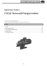
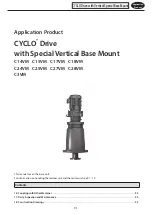
Application
Product
CAUTION
- When coupling the gearmotor or reducer with a load, check that centering is within the specified limits. Correctly tighten
bolts on the coupling before operation; otherwise, injury may result because of misalignment.
- Confirm the rotation direction before coupling the unit with the driven machine. For C15VM, C18VM, C25VM and C28VM,
check the direction of the shaft end screw. (Standard specification is left-handed screw.) Incorrect rotation direction may
cause personal injury or damage the equipment.
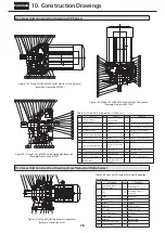
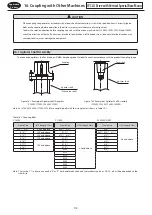
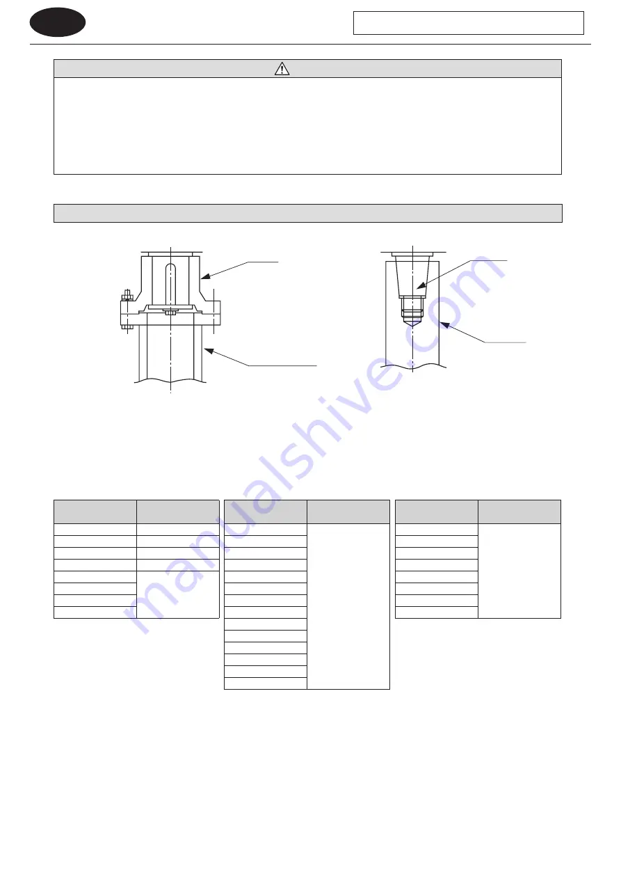
16-1 Agitator Shaft Assembly
The connected agitator’s shaft end shape will differ based on product model. Connect in accordance with the product’s coupling shape.
Coupling
Agitator shaft
(When pipe shaft)
Agitator shaft
Taper shaft
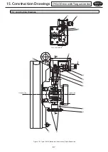
Figure 16-1 Example of Agitator Shaft Assembly
(C14VM, C17VM, C24VM, C27VM)
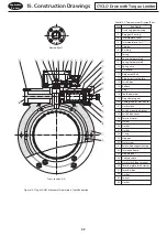
Figure 16-2 Example of Agitator Shaft Assembly
(C15VM, C18VM, C25VM, C28VM)
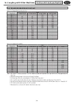
Note : For C14VM, C24VM, C17VM, C27VM, use coupling bolts with the strength class shown in Table 16-1.
Table 16-1 Coupling Bolts
C14VM
C17VM
C24VM, C27VM
Frame Size
JIS Strength Class
Frame Size
JIS Strength Class
Frame Size
JIS Strength Class
609
□
, 610
□
8.8 and above
609
□
, 610
□
8.8 and above
608
□
8.8 and above
612
□
12.9 and above
612
□
609
□
, 610
□
, 611
□
613
□
10.9 and above
613
□
, 614
□
612
□
614
□
12.9 and above
616
□
613
□
616
□
10.9 and above
617
□
614
□
617
□
618
□
616
□
618
□
619
□
617
□
619
□
6205
618
□
6215
6225
6235
6245
6255
6265
Note : The symbol
□
in frame size can be “0” or “5”. For double reduction and triple reduction types, DA, TA, etc. will be appended to the
frame size.
16. Coupling with Other Machines
CYCLO Drive with Vertical Special Base Mount


