

93
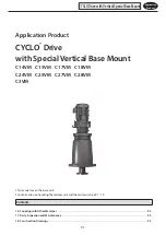
Application
Product
16. Coupling with Other Machines
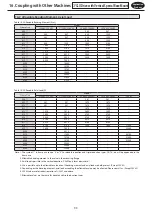
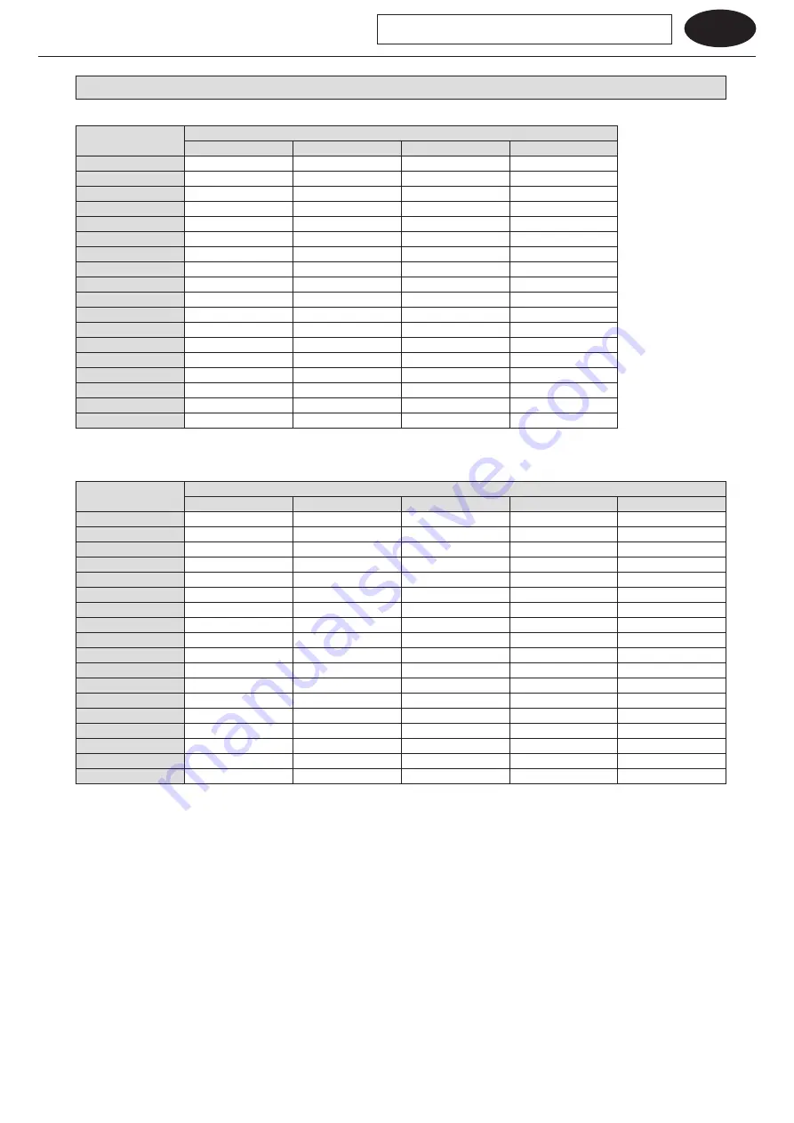
16-2 Allowable Bending Moment, Axial Load
Table 16-2 Allowable Bending Moment (N
・
m)
Frame Size
Model
C14VM, C15VM
C17VM, C18VM
C24VM, C25VM
C27VM, C28VM
608
□
−
−
343
687
609
□
343
687
638
1230
610
□
343
687
638
1230
611
□
−
−
638
1230
612
□
638
1230
1080
2160
613
□
1080
2160
1570
3140
614
□
1080
2160
1570
3140
616
□
1570
3140
2260
4410
617
□
2260
4410
2940
5890
618
□
2940
5890
3830
7550
619
□
3830
7550
−
−
6205
−
10800
−
−
6215
−
13700
−
−
6225
−
15700
−
−
6235
−
18600
−
−
6245
−
24500
−
−
6255
−
31400
−
−
6265
−
37300
−
−
Table 16-3 Allowable Axial Load (N)
Frame Size
Model
C14VM, C15VM
C17VM, C18VM
C24VM, C25VM
C27VM, C28VM
C3VM
608
□
−
−
981
981
−
609
□
981
981
1670
1670
−
610
□
981
981
1670
1670
−
611
□
−
−
1670
1670
−
612
□
1670
1670
2650
2650
−
613
□
2650
2650
3730
3730
−
614
□
2650
2650
3730
3730
−
616
□
3730
3730
4910
4910
−
617
□
4910
4910
6180
6180
−
618
□
6180
6180
7650
7650
21600
619
□
7650
7650
−
−
32400
6205
−
9810
−
−
−
6215
−
11800
−
−
46100
6225
−
13700
−
−
51000
6235
−
15700
−
−
51000
6245
−
20600
−
−
−
6255
−
24500
−
−
−
6265
−
29400
−
−
−
Note : 1. The symbol
□
in frame size can be “0” or “5”. For double reduction and triple reduction types, DA, TA, etc. will be appended to the
frame size.
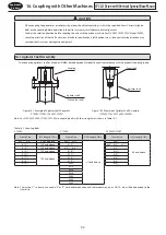
2. Allowable bending moment is the value in the mounting flange.
3. Axial load is possible in the vertical direction. (C3VM only faces downward.)
4. Use is possible up to the allowable value, even if bending moment and axial load are both present. (Except C3VM.)
5. Depending on the bending moment, axial load exceeding the allowable value may be allowed. Please consult us. (Except C3VM.)
6. C3VM values are for reduction ratios of 1/2537 and above.
7. Allowable values are the same for double and triple reduction types.
CYCLO Drive with Vertical Special Base Mount


