Installation
22
2.2
Look through the “peep hole” on the container. View the pressure gauge on the
Compressor Unit front panel. The pressure gauge should indicate equalization
pressure shown in specification section.
2.3
If the gauge indicates 0 PSIG (0 MPa), the Compressor Unit cannot be used.
Contact the nearest SHIG Service Center.
3.
Upon receipt, inspect Tip-N-Tell Sensor on Package for Activation
3.1
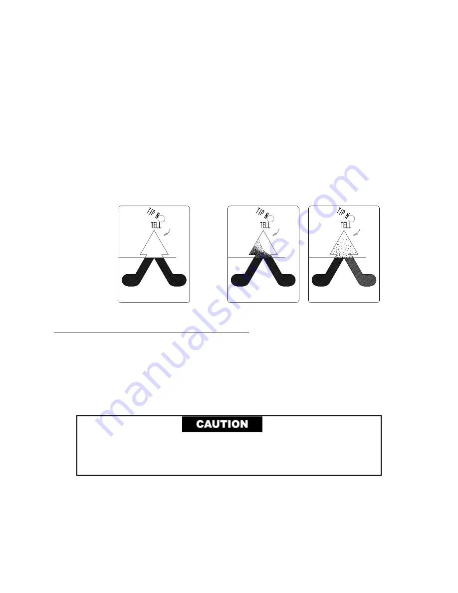
The Tip-N-Tell sensor mounted on the shipping container package surface should be
checked upon receipt and before unpackaging to verify the “Compressor Unit
shipping container” was NOT tipped or mishandled during transport.
3.2
If activated, Tip-N-Tell sensor turns blue in the arrow as shown below. Proceed with
internal inspection.
Non-Activated (Good) Activated (Not Good)
Unpackaging and Product Inspection Instructions
1.
Unpackaging Instructions
1.1
Remove the straps around the package.
1.2
Remove the Packaging Cover Shell and Top Inside Cushions.
1.3
Insert and tighten the three (3) furnished eyebolts into the top of the compressor.
See Figure 3.
PREVENT EQUIPMENT DAMAGE.
Use properly rated commercial
equipment for lifting or moving the compressor. Make sure compressor is
held in a balanced and stable position. Follow all applicable safety
procedures for overhead material transport.
1.4
Carefully lift the compressor off the wooden base.
1.5
Retain the reusable shipping container parts for possible reuse. This includes the
wooden base with Ethafoam cushion blocks, the packaging cover shell and the top
inside cushions.
Summary of Contents for F-20L
Page 2: ......
Page 10: ...6 This page is intentionally blank...
Page 12: ...8 This page is intentionally blank...
Page 23: ...Specifications 19 Figure 2 F 20L Compressor Front View...
Page 24: ...Specifications 20 Figure 3 F 20L Compressor Dimensions Dimensions are in inches and mm...
Page 34: ...30 This page is intentionally blank...
Page 36: ...32 This page is intentionally blank...
Page 48: ...44 This page is intentionally blank...
Page 53: ...Troubleshooting 49 Figure 19 F 20L Compressor Wiring Diagram...
Page 54: ...Troubleshooting 50 Figure 20 F 20L Compressor Wiring Schematic...


