Maintenance
40
To charge helium gas to the system:
1.
Stop the compressor.
2.
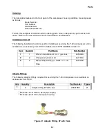
Locate charge and vent tool, P/N 267191A, and bleed adapter, P/N 267192A. Screw
bleed adapter into charge and vent tool.
3.
Connect the charge line from the pressure regulator of a helium gas cylinder containing
99.999% pure helium with a dew point less than -62° C (-80° F) at 20.7 bar (300 psig) to
Swagelok connector on charge and vent tool, P/N 267191A.
4.
Slightly open charge and vent tool's valve and thoroughly purge the charge line from the
regulator. It is important to remove all air contaminants to prevent them from
entering the system.
5.
Unscrew the self-sealing coupling on the bleed adapter, P/N 267192A, from the
charge and vent tool, P/N 267191A. Close the valve.
6.
Use two wrenches to attach the charge and vent tool to the 4M Aeroquip helium
charge port on the front of the compressor.
7.
Adjust the regulator to the required equalization pressure. See the Specifications section.
Slowly
open the valve on the charge and vent tool. Charge the system with helium gas to
the equalization pressure.
8.
Close the valves on the charge and vent tool and on the gas cylinder.
9.
Disconnect the charge line from the charge and vent tool. Using two wrenches,
remove the charge and vent tool. Store the charge line to keep it clean.
10.
Leak check the Aeroquip couplings using the Leak Check procedure in this manual
This completes the charging procedure.
Venting Procedure to Adjust the Equalization Pressure
NOTE
This venting procedure is not to be used for gas cleanup of the compressor.
To vent helium gas from the system:
1.
Stop the compressor.
2.
Be sure the valve on the charge and vent tool, P/N 267191A, is closed. Using two
wrenches, install this tool on the 4M Aeroquip helium charge port.
3. Slowly
open the valve on the charge and vent tool. Vent the system until the required
equalization pressure is attained. See the Specifications section. Close the valve on the
tool.
4.
Using two wrenches, remove the charge and vent tool from the compressor.
This completes the venting procedure to adjust the equalization pressure.
Summary of Contents for F-20L
Page 2: ......
Page 10: ...6 This page is intentionally blank...
Page 12: ...8 This page is intentionally blank...
Page 23: ...Specifications 19 Figure 2 F 20L Compressor Front View...
Page 24: ...Specifications 20 Figure 3 F 20L Compressor Dimensions Dimensions are in inches and mm...
Page 34: ...30 This page is intentionally blank...
Page 36: ...32 This page is intentionally blank...
Page 48: ...44 This page is intentionally blank...
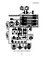
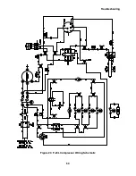
Page 53: ...Troubleshooting 49 Figure 19 F 20L Compressor Wiring Diagram...
Page 54: ...Troubleshooting 50 Figure 20 F 20L Compressor Wiring Schematic...


