MAINTENANCE
13
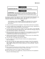
AVOID EXPOSURE.
People with pacemakers, defibrillators or ferrous implants
should avoid exposure to strong magnetic fields. The long-term effects of high
magnetic fields are not well understood. Keep personal exposure to a minimum.
AVOID INJURY.
When released in a high magnetic field, ferrous tools and parts
can become hazardous projectiles.
PREVENT DEGRADED PERFORMANCE.
Failure to replace the adsorber can
result in oil carryover to the cold head, degraded performance and difficult oil
cleanup.
AVOID CONTAMINATION.
A leaking coupling on an adsorber should not be
repaired in the field. Consult a Service Center. Venting the adsorber will
introduce contaminants to the system that cannot be removed in the field.
PRESERVE YOUR WARRANTY.
Modification to equipment without the consent
of the manufacturer will void the warranty.
Specifications require the use of 99.999% pure helium gas. Using a lesser quality
of helium can damage the system and void the warranty.
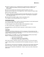
Connect and Remove the Water Lines
Tools required: Open-end wrench, 15/16”
Open-end wrench to suit customer’s water lines fittings
1.
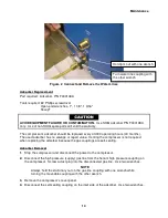
Using two wrenches, connect coolant supply and return lines to the water in and water out
fittings on the front of the compressor. See Figure 2. Ensure that the Water In connection is
connected to the supply line from the user’s cooling water or coolant supply. Turn on the
coolant and check the water lines for leaks. Tighten the fittings if necessary.
See Specifications in the F-70 Operating Manual for cooling requirements.
Summary of Contents for F-70H
Page 2: ......
Page 8: ...4 This page is intentionally blank...
Page 10: ...6 This page is intentionally blank...
Page 12: ...8 This page is intentionally blank...
Page 14: ...10 This page is intentionally blank...
Page 28: ...24 This page is intentionally blank...
Page 40: ...Troubleshooting 36 Figure 4 F 70H Compressor Wiring Diagram...
Page 41: ...Troubleshooting 37 Figure 5 F 70H Compressor Wiring Schematic...
Page 42: ...Troubleshooting 38 Figure 6 F 70L Compressor Wiring Diagram...
Page 43: ...Troubleshooting 39 Figure 7 F 70L Compressor Wiring Schematic...

