Troubleshooting
28
1.
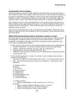
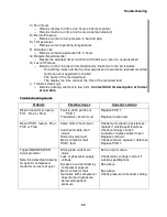
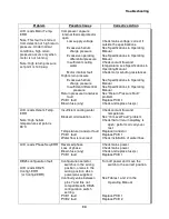
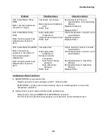
Read and record the elapsed time on the LCD display of the old unit. Contact a Service
Center to report the elapsed time meter reading.
AVOID ELECTRIC SHOCK.
Disconnect the power to the compressor before
troubleshooting the electrical components.
2.
Stop the compressor and disconnect the power to the compressor.
3.
Using a Phillips screwdriver, remove the compressor’s cover. Retain the screws and lock
washers for reinstallation.
4.
Remove the electrical chassis ventilated cover by using a Phillips screwdriver to remove the
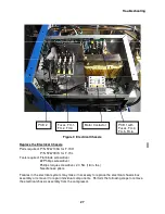
6 screws and lock washers. See Figure 3. Retain the screws and lock washers.
5.
Using a flat blade or a Phillips screwdriver, remove the 3 wires from terminals T1, T2 and T3
on the motor contactor. Remove the wire clamp and wire tie. Remove the ground wire from
the green ground screw.
6.
Disconnect the solenoid wires from the printed circuit board. Connector is not visible behind
the transformer in Figure 2. Remove the wire tie from the solenoid wires.
7.
Disconnect from the printed circuit board the sensor connectors on the outside of the
electrical chassis box
8.
Remove the four screws and lock washers on the front panel of the electrical chassis.
Retain the screws and washers. Remove the two screws and lock washers holding the
electrical chassis to the compressor’s mounting frame.
9.
Pull the disconnected wires through the bushing in the rear of the electrical chassis.
Carefully pull the front panel of the electrical chassis away from the front panel of the
compressor. Completely remove the electrical chassis.
10.
Install the new electrical chassis. Reconnect the wires, clamps and wire ties removed in
steps 5, 6 and 7. Refer to the wiring schematic. Proper phasing requires connecting wire 4
to T1, wire 5 to T2 and wire 6 to T3. Using a Phillips torque screwdriver, tighten the wires to
the contactor’s terminals to 2.0 Nm (18 in. lbs.).
11.
Replace the compressor’s cover.
12.
Reconnect the power to the compressor.
13.
Start the compressor to check that it runs properly.
This completes the procedure for replacing the electrical chassis.
Contact SCAI Engineering for procedure on resetting time on F-70 compressor.
Replace the Supply Gas High Temperature Thermistor
Part required: Gas temperature thermistor, P/N 267049A
Tools required: #0 Phillips screwdriver
#2 Phillips screwdriver
Needle nose pliers
1.
Stop the compressor and disconnect the power to the compressor.
Summary of Contents for F-70H
Page 2: ......
Page 8: ...4 This page is intentionally blank...
Page 10: ...6 This page is intentionally blank...
Page 12: ...8 This page is intentionally blank...
Page 14: ...10 This page is intentionally blank...
Page 28: ...24 This page is intentionally blank...
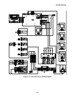
Page 40: ...Troubleshooting 36 Figure 4 F 70H Compressor Wiring Diagram...
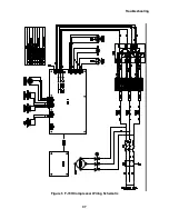
Page 41: ...Troubleshooting 37 Figure 5 F 70H Compressor Wiring Schematic...
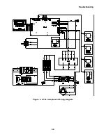
Page 42: ...Troubleshooting 38 Figure 6 F 70L Compressor Wiring Diagram...
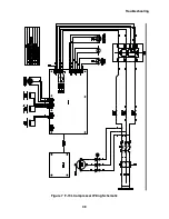
Page 43: ...Troubleshooting 39 Figure 7 F 70L Compressor Wiring Schematic...

