Troubleshooting
49
2.
Remove the compressor’s cover.
3.
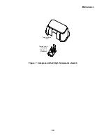
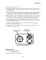
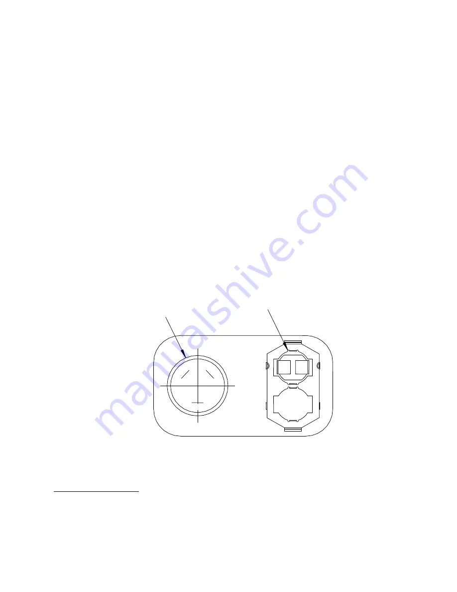
Remove the terminal box cover from the top of the compressor motor to expose the three
terminals M, S, and C. See Figure 8. Disconnect wires 7, 8, and 9 from terminals C, M,
and S respectively.
4.
With an ohmmeter, check the resistance across compressor terminals C and M. Resistance
should be 0.8 to 1.2 ohms. If the resistance is outside this range, consult a SCAI Service
Center. If there is no continuity, the winding is open. Consult a SCAI Service Center.
5.
With an ohmmeter, check the resistance across compressor terminals C and S. Resistance
should be 1.8 to 2.2 ohms. If the resistance is outside this range, consult a SCAI Service
Center. If there is no continuity, the winding is open. Consult a SCAI Service Center.
6.
With an ohmmeter, check for continuity between compressor terminal C and one of the
copper tubes entering the compressor housing. If there is continuity, the motor is grounded.
Consult a SCAI Service Center.
7.
If the motor passes these electrical checks, reconnect wires 7, 8, and 9 to compressor
terminals C, M, and S respectively.
8.
Replace the terminal box cover and the cover of the compressor module, unless current
measurement is to be performed.
Figure 8 Compressor Terminals
Current Measurement
Tools required: #2 Phillips screwdriver
Clamp-on ammeter
1.
Disconnect the power to the compressor
S
C
M
Temperature
Overload Switch
Compressor Motor
Terminals
Summary of Contents for HC-4E1
Page 2: ......
Page 8: ...4 This page is intentionally blank...
Page 10: ...6 This page is intentionally blank...
Page 12: ...8 This page is intentionally blank...
Page 20: ...16 This page is intentionally blank...
Page 26: ...22 This page is intentionally blank...
Page 38: ...34 This page is intentionally blank...
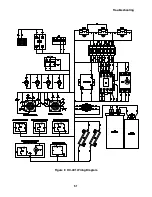
Page 55: ...Troubleshooting 51 Figure 9 HC 4E1 Wiring Diagram...
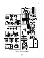
Page 56: ...Troubleshooting 52 Figure 10 HC 4E2 Wiring Diagram...
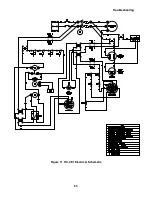
Page 57: ...Troubleshooting 53 Figure 11 HC 4E1 Electrical Schematic...
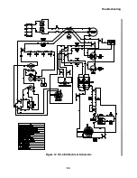
Page 58: ...Troubleshooting 54 Figure 12 HC 4E2 Electrical Schematic...
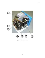
Page 61: ...Parts 57 Figure 13 Parts Identification 18 21 19 13 14 20 16...

