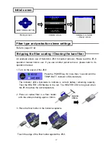
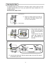
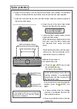
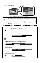
background image

Cleaving the fiber 

An example shows use of Sumitomo FC-6M fiber cleaver. Please read the FC-6M 
operation manual before use. If you use another fiber cleaver, please refer to its 
operation manual. 

Standard cleave length: 10mm     

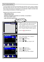
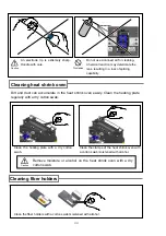
1-1: Open the coating clamp lid and the top 

clamp lever. The blade carriage should 
be in the forward position. 

Blade carriage 

1: 

2: 

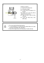
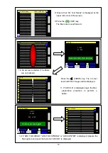
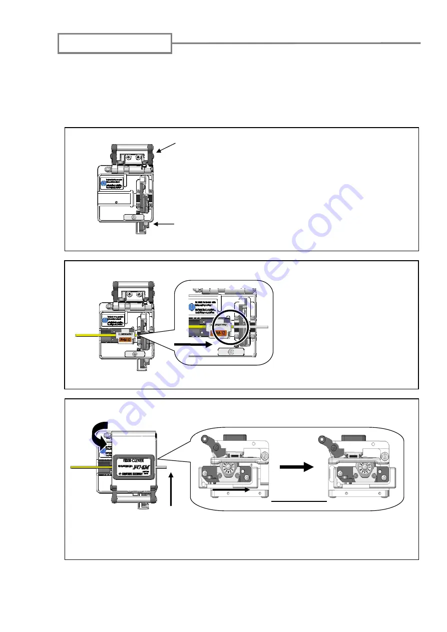
2-1: Place the fiber holder in the 

FC-6M. (Touch the edge of 
the fiber holder against the 
FC-6M.)  
* Keep the fiber in the fiber 
holder after stripping the 
fiber coating/cleaning the 
bare fiber. 

3: 

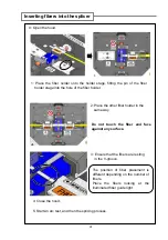
3-1: Lower the top clamp lever. Slide the blade carriage to the rear of the cleaver 

as indicated by the arrow. 

Cleave the fiber 


Top clamp lever


19 

Summary of Contents for TYPE-66M12

Page 1: ...OME0724004H Mass Fusion Splicer TYPE 66M12 Guide to operation Sumitomo Type 66M12 Specs Provided by www AAATesters com...

Page 2: ...bol indicates actions that are prohibited This symbol indicates actions that must be taken The meaning of Warning and Caution This symbol indicates explanations about extremely dangerous matters If us...

Page 3: ...ys use the connection method as defined in this manual Failure to do so may cause a fire or electric shock 11 Only use a voltage within the indicated power voltage Failure to do so may cause a fire or...

Page 4: ...store the battery together with any personal jewelry hairpins or other Metallic objects Doing so can cause an electrical short circuit Also excessive current flow may cause abnormal chemical reaction...

Page 5: ...airpins or other metallic objects Doing so can cause an electrical short circuit Also excessive current flow may cause abnormal chemical reaction in battery heat generation bursting and fire 3 Do not...

Page 6: ...European Union member states The crossed out wheelie bin symbol found on our products indicates that it should not be disposed of together with household waste To prevent possible harm to human healt...

Page 7: ...r or disclose the whole or part of the writings to the public or unidentified parties and transfer disclose or display the electrical format of the writings through online media 2 make copy of the wri...

Page 8: ...Notification of North American patents on the TYPE 66 U S Patents 4 812 010 5 777 867 6 287 020 6 437 299 6 518 551 6 519 405 CANADA Patents 2 183 840 2 321 400...

Page 9: ...tery charging 13 DC operation car battery 14 Battery refreshing 14 Precautions for battery module 14 Operating procedures 16 Turning on the TYPE 66 16 Initial screen 17 Fiber type and protection sleev...

Page 10: ...intenance settings 45 5 Other convenient functions 46 Back monitor type 46 Dual heat shrink oven 46 Detachable attachable bare fiber pads 47 Auto start 47 Splice data storage function 48 Tripod fixing...

Page 11: ...25 m Fiber count 1 2 4 5 6 8 10 12 Cleave length 10mm The TYPE 66 key features are Dual heat shrink oven For more information see page 46 2 heat shrink ovens are equipped with the fusion splicer The o...

Page 12: ...ooling tray 1 pc 7 Spare electrodes ER 10 1 pair 8 Operation manual 1 OME0724004 1 pc 9 Quick reference guide 1 OME0724004 2 1 pc 10 Carrying case CC 66 1 pc The above package is an example The packag...

Page 13: ...d up to 12 fiber ribbon Jacket remover JR M03 Applicable fiber Single fiber Applicable coating diameter 250 m 900 m Hot Jacket remover JR 6 Applicable fiber single fiber and up to 12 fiber ribbon Repl...

Page 14: ...me and usage and are replaceable by a customer Therefore they will not be covered under warranty Monitor Monitors are considered a component that degrades and is deteriorated with time and usage Sumit...

Page 15: ...o heat and shrink fiber protection sleeves 2 heat shrink ovens front and rear are equipped Power module bay Power supply or battery module is installed Input output panel DC output terminal for hot ja...

Page 16: ...page and display key guidance Power key LED Used to turn on and off the splicer LED illuminates while the splicer is on SET key Starts a splicing operation RESET key Used to cancel a splicing operatio...

Page 17: ...mirrors from any dust or dirt Fiber holder stage A fiber holder is placed on the stage 2 3 Fiber guide A small green light is illuminated for easy fiber placement 4 Electrodes Arc is generated between...

Page 18: ...tion sleeve 2 Heat shrink oven clamps Hold fiber straight Input output panel 3 1 2 Video output terminal Used for an external monitor 3 DC output terminal Used to supply DC power to a hot jacket remov...

Page 19: ...ce with the fusion splicer For further information on each step please see the page described below Turning on the TYPE 66 Page 16 Initial screen Page 17 Starting the automatic splice Page 25 9 Mainte...

Page 20: ...y module PS 66 into the module bay Installation Insert the power supply module PS 66 into the module bay and slide forward until it locks into space Removal 1 While pressing the release button located...

Page 21: ...Using an unused battery module 1 splice cycle shall be completed in 90 seconds in room temperature without using a heated jacket remover If the power is turned on after the battery module is installe...

Page 22: ...button The LED will light up for a few seconds to indicate the battery status in one of four levels Indicator Battery level The battery level is also displayed by the battery level indicator on the m...

Page 23: ...ule can be charged while installed in the splicer but the power cannot be turned on When charging is complete remove the battery module from the splicer and re install it 3 Charge the battery module w...

Page 24: ...y turned off Connect the PS 66 power supply module to the BU 66 battery module for charging Battery Refresh PAGE MOVE SELECT Refresh time depends on the amount of charge remaining in the battery modul...

Page 25: ...ng to use the battery module for a long period charge the battery module once every 6 months To extend battery life refresh the battery module once a month When should the battery be replaced If you a...

Page 26: ...on monitors The monitor viewing angle can be adjusted Power cord 1 Prepare the power supply referring to page10 15 2 Adjust the monitor for optimum viewing angles 3 Press the power key for more than...

Page 27: ...MITOMO ELECTRIC INDUSTRIES LTD Initialize is complete Ready screen Ready SM 12c 40mm 12c Y Press the POWER key for more than 1 second until the TEMP BATT indicator LEDs illuminate 2 Place an optical f...

Page 28: ...he convex portion of the fiber holder 6 The fiber coating is removed Take out the fiber holder from the JR 6 9 Repeat the stripping and cleaning processes for the other fiber 8 Lightly brush the ends...

Page 29: ...g clamp lid and the top clamp lever The blade carriage should be in the forward position Blade carriage 1 2 2 1 Place the fiber holder in the FC 6M Touch the edge of the fiber holder against the FC 6M...

Page 30: ...ends insert each fiber immediately after preparation 3 Glass fiber fragments are extremely sharp Handle with care 4 2 Lift the fiber holder 4 3 Lift the off cut and dispose of it properly Be careful n...

Page 31: ...ing the pin of the fiber holder stage into the hole of the fiber holder Do not touch the fiber end face against any surface Inserting fibers into the splicer 0 Open the hood 3 Ensure that the fibers a...

Page 32: ...t 1 Strip the coatings clean cleave and insert the fibers Hereinafter called prepare the fiber After initialization check to see if the displayed fiber type and protection sleeve type are correct if n...

Page 33: ...er again and repeat the test until ARC OK is displayed Press the FIBER key The arc test result with fiber images will be displayed Arc Test Ready SM 12c 40mm 12c Y Arc SM 12c 40mm 12c Y Arc OK FIBER L...

Page 34: ...arc test Prepare the fiber again Start splicing Fiber preparation 1 Be sure to slip the fiber protection sleeve over one of the fibers to be spliced before stripping and cleaving the fibers The fiber...

Page 35: ...ck 0000 Y Y X Arc Count is displayed on the screen Y X Open Hood Ave 0 01dB 3 5 1 2 4 6 7 0 01 0 01 0 01 0 01 0 01 0 01 0 01 0 01 0 01 0 01 0 01 0 01 9 8 11 10 12 Open Hood is displayed Proof test is...

Page 36: ...8 10 PAGE MEMO BACK Offset CutL CutR Gap 1 2 2 0 1 0 5 0 2 35 1 Irregular R 010 L 013 3 0 7 0 6 0 5 35 6 4 0 3 0 8 0 7 39 6 9 0 9 0 7 0 5 35 1 10 0 1 0 5 0 3 35 1 11 0 6 0 7 0 2 36 9 12 0 8 0 3 0 4 3...

Page 37: ...spliced fiber to be broken resulting in loss of the long term reliability of the fiber Y X Ave 0 01dB Estimation Loss 3 5 1 2 4 6 7 0 01 0 01 0 01 0 01 0 01 0 01 0 01 0 01 0 01 0 01 0 01 0 01 9 8 11...

Page 38: ...6 7 0 01 0 01 0 01 0 01 0 01 0 01 0 01 0 01 0 01 0 01 9 8 11 10 0 01 12 Evaluating splice quality If the spliced fiber is as follows or estimated losses are high re do the entire splice White line Bul...

Page 39: ...open together 1 Open the hood and the lid of the one fiber holder Slide the protection sleeve to the center of the splice Rear Front Rear Front 4 Press the HEAT key to start the shrinking process The...

Page 40: ...t Handle with care Never touch the surface of the heating plate during the heating operation Doing so may cause personal injury and damage to the heat shrink oven Caution Evaluating protection sleeve...

Page 41: ...ause electric shock Clean each part with a cotton swab Please bear in mind that daily cleaning can maintain splicer performance Clean components before and after use Names of components 3 Maintenance...

Page 42: ...clean them with a cotton swab moistened with alcohol Do not use a canned air for cleaning Chemical reaction may deteriorate the 32 lens resulting in a loss of splicing capability 1 Prepare a cotton s...

Page 43: ...ly too much force when cleaning Cleaning microscopes objective lenses If an unclear fiber image is still displayed or LED error occurs again after cleaning LEDs or a mirror protection glass clean the...

Page 44: ...n accumulate in the heat shrink oven easily Clean the heating plate regularly with a dry cotton swab Clean the heating plate with a dry cotton swab Caution Remove moisture or alcohol on the heat shrin...

Page 45: ...bscrews 3 Lift the electrode cover plate as shown in the left figure 4 Remove the old electrode 5 Install a new electrode When handling the electrodes avoid touching the electrode tips with anything C...

Page 46: ...ble arcing performance Caution Replacing monitor protection panel The damaged or contaminated monitor protection panel can be replaced 1 Unscrew the 4 screws to remove the monitor protection panel 2 F...

Page 47: ...ansport the machine in its case Observe the following instructions Clean the TYPE 66 and all accessories before storing them Be sure to remove the battery from the TYPE 66 and store it in a given plac...

Page 48: ...with care Caution Close the carrying case completely and latch it before transportation Pay attention to storage temperature and dew condensation when storing the splicer The battery module is self d...

Page 49: ...the details of heater conditions refer to page 40 If you would like to change heater condition parameters refer to page 42 In this screen monitor brightness can be adjusted if the Brightness control k...

Page 50: ...U T G 651 DSM 1c Can be used for splicing dispersion shifted single fiber ITU T G 653 Can be used for splicing dispersion shifted 2 fiber ribbon ITU T G 653 DSM 2c Can be used for splicing dispersion...

Page 51: ...40 dot BACK MOVE SELECT PAGE OFF Heating Duration A 22 sec 230 C Heat up Temp B 200 C Heating Duration B 05 sec Finish Temp 150 C BACK MOVE SELECT PAGE Press the key to display key Fusion Time 3 3 Pre...

Page 52: ...perature it maintains the temperature of both ends for this duration Finish Temp This is the finish temperature to take out the sleeve The flashing indication on the keypad stops at this temperature a...

Page 53: ...ight for v groove ON Date dd mm yy hh mm 12 02 07 17 00 PAGE 1 Use the MOVE keys to select the function you would like to change 2 Use the SELECT key to change the settings 3 Press the PAGE key to go...

Page 54: ...function switches the temperature units Heater Auto Start This function starts the heating process when the fiber is placed into the heat shrink oven Light for V groove This function sets the V groove...

Page 55: ...BACK 1 2 Conditioning Arc Reset Arc Count Maintenance when electrodes changed Maintenance 2 2 Restore Data Self Inspection Battery Refresh MOVE SELECT PAGE BACK Ready SM 12c 40mm 12c Y Maintenance Pag...

Page 56: ...See also page 43 44 Back 46 Dual heat shrink oven 2 heat shrink ovens are equipped with the TYPE 66 The ovens run individually and splicing operation can be improved more effectively Both ovens also...

Page 57: ...ned the bare fiber pad is removed from the hood 3 You can check if the fiber is placed seated in the V groove properly by the pad 4 When the hood is closed the hood catches the bare fiber pad The hood...

Page 58: ...would like to view Description of data Offset Inspected offset of diameter axis CutL Inspected cleave angle of left fiber CutR Inspected cleave angle of right fiber Gap Inspected arc gap Offset CutL...

Page 59: ...the splicer to a tripod to prevent it from dropping Screw hole for M8 screw Screw hole for 1 4 20UNC screw In a high location fix the TYPE 66 to a tripod with the M8 screw or 1 4 20UNC screw on the b...

Page 60: ...ks If the fibers are breaking when the proof test is performed re do an arc test If the arc power level is too weak the splice may be poor resulting in fiber breaking If the fibers are breaking in spi...

Page 61: ...d by drop fall or any other faulty treatment such as to be explained in precautions on this manual 3 Damage or malfunction caused by actions that are beyond Sumitomo s control including for example fi...

Page 62: ...R Measure Turn off the power and turn it on again If the error still persists contact our maintenance service center Cut Error Angle Description L R LR The cleave angle exceeds the allowable level Mea...

Page 63: ...Description L R LR The fiber is not placed in the V groove properly Measure Place the fiber in the V groove again Fiber Count Error Description L R LR The number of the fiber being spliced is differen...

Page 64: ...ption Splice Error The spliced portion has a problem Splice Thin Thin Thick 1 The irregularity of the fiber end is high Neck 2 The Overlap value is low Bubble 3 The arc power is strong Thick 1 The irr...

Page 65: ...rox 45 seconds FPS 6 12 fiber ribbon Approx 75 seconds Splice heat cycles per fully charged battery 4 Approx 80 BU 66S Approx 160 BU 66L Loss Estimation Provided Splice data storage 2 000 splices Func...

Page 66: ...ng on the temperature and the remaining battery capacity 4 With a new battery 1 splice cycle time splice protection completes in 90 seconds in room temperature A hot jacket remover is not used Splice...

Page 67: ...57...

Page 68: ...omo Electric Consulting Sumitomo Electric Lightwave Corp Shanghai Co Ltd 78 Alexander Drive P O Box 13445 Research Triangle park New Delhi India Tel 86 21 6278 5978 NC27709 U S A Sumitomo Electric Ind...

Reviews: