background image

L3214 Laser Cutter 


User’s Manual


Starting up the laser cutter 

32 

3


STARTING UP THE LASER CUTTER 

1.


Check  whether  maintenance  tasks  need  to  be  performed.  For  more  information,  see 
chapter 4 

Maintenance 

on page 33. 

2.


Make sure the power supply to the laser cutter is switched on.  

3.


Power on the laser cutter.  

The loading screen is displayed, and the motion system moves to its home position.  

Then, the home screen is displayed. 
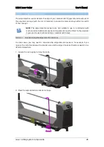
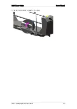
4.


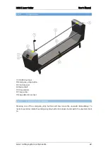
Load the roll of material on the unwinder (for more information, see chapter 2.4 

Loading 

the roll of material on the unwinder

 on page 29). 

5.


Open GoProduce Laser Edition to start your cutting job (more information on working with 
the software can be found in the GoProduce Laser Edition user manual). 


Summary of Contents for L3214

Page 1: ...L3214 LASER CUTTER User Manual Rev 002...

Page 2: ...et out in the Radio Interference Regulations of the Canadian Department of Communications Notice Summa reserves the right to modify the information contained in this User Manual at any time without pr...

Page 3: ...oduct registration Failure to register the L3214 laser cutter may result in a delayed response to warranty and service inquiries Contact Information All inquiries comments or suggestions concerning th...

Page 4: ...flawless finishing and absolutely nothing cuts as accurately as lasers do The contactless cutting method of laser equipment means no fabric distortion low to no dust generation no tool wear and no fra...

Page 5: ...el 14 2 1 1 1 Home screen 14 2 1 1 2 Settings screen 15 2 1 1 3 Laser Test Fire Screen 16 2 1 1 4 Media Area Screen 17 2 1 2 Conveyor system 18 2 1 3 Finger safety conveyor cover 18 2 1 4 Safety cover...

Page 6: ...38 4 1 1 6 Cleaning the cutting head mirror 41 4 1 2 Pneumatics 43 4 1 2 1 Cleaning the nozzle 43 4 1 2 2 Setting the nozzle height 44 4 1 2 3 Adjusting airflow 45 4 1 2 4 Emptying the water collectio...

Page 7: ...anty The installation of the machine accessories and spare parts must not be done by untrained or unauthorized persons Also the described maintenance procedures need to be followed and performed by tr...

Page 8: ...extended period of time Caution Class 1 Laser Product Class 4 invisible laser radiation when open Avoid eye or skin exposure to direct or scattered radiation Class 2 laser pointer Do not stare into t...

Page 9: ...leave it unattended at any time 1 1 4 2 Safety precautions related to movement WARNING There is a risk of injury from being caught or trapped in moving machine parts Keep hands hair clothing and jewe...

Page 10: ...4 laser cutter can process a broad range of materials Choose only material types that do not generate harmful emission during the cutting process Check with the material supplier or manufacturer befor...

Page 11: ...lothing Respirator mask in case of toxic fumes Safety goggles when processing the material harmful particles can be generated 1 2 Operating environment Environmental conditions can significantly affec...

Page 12: ...3214 Laser Cutter User s Manual Laser cutting system components 12 2 LASER CUTTING SYSTEM COMPONENTS Laser cutter Edge detection unwinder Water chiller Extractor fans vacuum and fume extraction 1 2 3...

Page 13: ...safety conveyor cover 4 Safety cover lid 5 Emergency stop buttons 6 Vision camera gantry 7 Pressure rollers 8 Feed button 9 Light switch camera gantry and cutting area 10 ON OFF buttons 11 Vision came...

Page 14: ...sections The working parameter limits of the machine are displayed in mm On the top right the cutter s status is indicated Use the arrow keys in the left section to move the cutting head around the c...

Page 15: ...ntensity displayed inbetween these buttons The system does not allow the vacuum setting to exceed the extraction setting o Ext extraction Use and to change extraction intensity displayed inbetween the...

Page 16: ...while the laser is firing Tap again to stop the move and fire action Tap to fire the laser once in its current position spot fire Tap to return to the Settings screen In case a move and fire actie is...

Page 17: ...ve the cutting head to the bottom right corner of the material 2 Press to confirm 3 Use the arrow keys in the left section to move the cutting head to the upper left corner of the material 4 Press to...

Page 18: ...ns on page 10 2 1 6 Vision camera gantry The L3214 laser cutter is equipped with the Vision camera gantry The Vision camera system uses integrated cameras to scan marks black outlines or barcodes fast...

Page 19: ...ne Before opening any covers to perform service or maintenance always switch off power using the main power switch 2 1 11 Ethernet connection Summa provides a computer in the right cabinet of the cutt...

Page 20: ...e opening the safety covers or investigating a malfunction Only authorised personal may then switch on the unwinder to investigate the problem Always turn off the unwinder before opening the electrics...

Page 21: ...after the laser cutter has been installed The unwinder must be placed parallel as central as possible in front of the back of the laser cutter and as close as possible to avoid stretching the material...

Page 22: ...gency stop button Control panel Media shaft Droop sensor Tension bar Edge detection sensor 2 2 3 1 Emergency stop buttons Pressing one of the emergency stop buttons will shut down the unwinder immedia...

Page 23: ...ic feeds from the roll loaded onto the media shaft Switch to the center to place the unwinder in park mode standby Error LED Flashes in the event of an error Automatic manual edge detection and tracki...

Page 24: ...lways exerts a small amount of tension however slight making it less suitable to use with very stretchy materials ATTENTION Do not lean on the tension bar when it is locked as this may damage the tens...

Page 25: ...vity and to the left it to reduce sensor sensitivity We recommend starting at maximum sensitivity and if necessary then turning the screw little by little to the left until the sensor detects the mate...

Page 26: ...sensors are not suitable to use in combination with mesh material Additional sensors and equipment must be fitted to the unwinder if you need to use mesh material or material with holes 2 2 3 4 1 Rep...

Page 27: ...L3214 Laser Cutter User s Manual Laser cutting system components 27 3 Secure the carriage by turning the knob again...

Page 28: ...an be expanded by means of air thus preventing even the slightest play of the roll of material on the media shaft The air gun for inflating the shaft is provided WARNING The recommended air pressure i...

Page 29: ...nder is set correctly 7 Make sure the pressure bar of the laser cutter lies in the upper supports so it cannot touch the material Place the material on the conveyor and as much in the middle as possib...

Page 30: ...using the arrow keys The normal coolant temperature ranges from 18 C to 25 C If the water temperature falls below the surroundings temperature condensation will form on the pipes and on the laser tube...

Page 31: ...tting process if it is set to Fans Manual FALSE in the Settings screen If you want to control the vacuum and fume extraction system s operation manually tap the setting to change it to Fans Manual TRU...

Page 32: ...r is switched on 3 Power on the laser cutter The loading screen is displayed and the motion system moves to its home position Then the home screen is displayed 4 Load the roll of material on the unwin...

Page 33: ...damaged The machine or parts of it has have been damaged by an impact Liquid was spilt on the machine or conveyor There is a strange noise smoke or an unusual smell coming from the machine Keep the l...

Page 34: ...with care and cleaned only with optical cleaning solution and an optical grade polishing cloth They must not be subjected to abrasives etc The working surfaces must not be handled directly Ideally gl...

Page 35: ...Ensure not to adjust the mirror position or apply too much pressure to the mirror so the bracket does not move out of alignment 4 1 1 2 Cleaning the travelling mirror The travelling mirror is firmly a...

Page 36: ...avelling mirror from their mount e g in the event of a defect and installing them again use the spanner wrench delivered in the toolbox 1 Place the spanner wrench on the mirror retaining washer so tha...

Page 37: ...source and the primary mirror Its purpose is to redirect the laser pointer into the same path as the cutting laser Remove the left hand side cover of the laser cutter using a cross key Apply a small a...

Page 38: ...lens with any sharp objects as this may damage the lens and reduce cutting efficiency Always use cloths that are moistened with IPA optical cleaning solution never use dry materials 1 Remove the cutti...

Page 39: ...sure that the area is sufficiently ventilated The solvent should be kept away from heat or flames Wear appropriate clothing and safety goggles Do not breathe in the fumes Avoid contact with skin and e...

Page 40: ...facing upward and carefully replace it into the machined recess of the barrel Lens convex surface uppermost 9 Ensure the lens is seated correctly such that the convex surface is facing upwards 10 Pla...

Page 41: ...nment is required 2 Gently rotate the head so that the mirror falls out onto the cleaning cloth 3 Apply IPA optical cleaning solution to the mirror face and let it soak for a few seconds 4 Gently lay...

Page 42: ...housing and secure it with the mirror securing clip and the mirror securing screw Ensure that the securing clip has a slight bend in it to ensure that the mirror is secured correctly Do not overtight...

Page 43: ...rel disassembled and the lens removed 1 Remove the cutting head by releasing the M3 cap head screw and detaching the pneumatic tube 2 Clean the hole using a wooden toothpick Use paper towel or a cloth...

Page 44: ...of the material that is processed height may vary 1 Loosen the thumb screw to adjust the height 2 Place the focusing gauge between the nozzle and the material When using a high pressure nozzle set the...

Page 45: ...3 51psi Inlet pressure bar 2 mm nozzle l min l h 0 5 7 2psi 45 4 2724 1 64 2 3852 1 5 80 3 4815 2 96 3 5778 2 5 112 4 6741 3 43 51psi 128 4 7704 4 Adjust the pressure by lifting the knob to unlock it...

Page 46: ...Y axis gearbox 2 Apply a small amount of light machine oil to a clean cloth and wipe the oil onto the toothed side of the white drive belt 3 Slowly move the cutting head towards the rear by pulling th...

Page 47: ...steps until all planks are clean 4 1 5 Water cooled laser unit The water cooled laser unit has been designed to be low maintenance Internal routine maintenance procedures are not required The system s...

Page 48: ...dicative 2 Visually inspect the inside of the fan and extraction hose Remove any debris and or large pieces of fabric 3 Refit the extraction pipe NOTE If the vacuum fails and the pump is spinning ther...

Page 49: ...er level The chiller needs a controlled water level to deliver full cooling capacity 1 Check the water level through the inspection glass The water level should be at least halfway Insufficient Suffic...

Page 50: ...to blow out the remaining water in the laser unit 4 Plug the blue tube back in 5 Flush the chiller with clean tap water once then close the drain valve 6 Refill the chiller with demineralized water Th...

Page 51: ...Cutter User s Manual Maintenance 51 2 Drain the water from the damaged water hose 3 Replace the water hose with a new one of the same length 4 Refit the water hose into the chiller and open both valve...

Page 52: ...re proper airflow through the chiller the grid and the air filter need to be free of dust The filter can be easily removed by hand 1 Lift the filter and tilt outwards to slide it out 2 Use a vacuum cl...

Page 53: ...al Reference Travelling Mirror Clean End User 1 Day Page 35 Head Mirror Clean End User 1 Day Page 41 Head Lens Clean End User 1 Day Page 38 Nozzle Clean End User 1 Day Page 43 Airflow Nozzle Check End...

Page 54: ...er Pipes Check End User 4 Weeks Page 50 Air Filter Clean End User 4 Weeks Page 52 Water Replace Dealer 6 Months Page 50 Service Service Local ICS Dealer 1 Year EXTRACTION SYSTEMS Component Task By Max...

Page 55: ...tandard 2 5 FL Lens 600 6028 Standard FB Mirror 600 6029 Diode Beam Combiner 600 6030 Optical Cleaning Fluid 600 6034 Optics Cleaning Cloth 600 6035 Alignment Kit Nozzle Alignment Tool Mirror Alignmen...

Page 56: ...gas needed The laser cutter switches on but the screen doesn t display antyhing The 3 amp fuse on the main elecrical panel has blown The laser won t switch on No mains power into the machine The mains...

Page 57: ...e properly Check the switches CANNOT INIT LID UP The lid is up before the homing sequence Check if the covers close properly Check the switches CANNOT INIT FRONT COVER Cover is open before the homing...

Page 58: ...GOCARE The GoCare software allows upgrading the laser cutter firmware making device and Vision camera backups and restoring machine settings The user manual of GoCare is available for download on our...

Page 59: ...s the perfect link between the design station RIP station printers and cutting devices Once the workflow is set up macros automate the process Consequently the number of times the operator has to inte...

Reviews: