S One
User’s Manual
Introduction
1-7
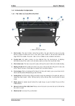
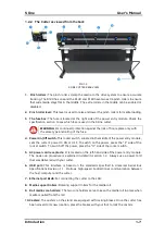
FIG 1-3
1-3
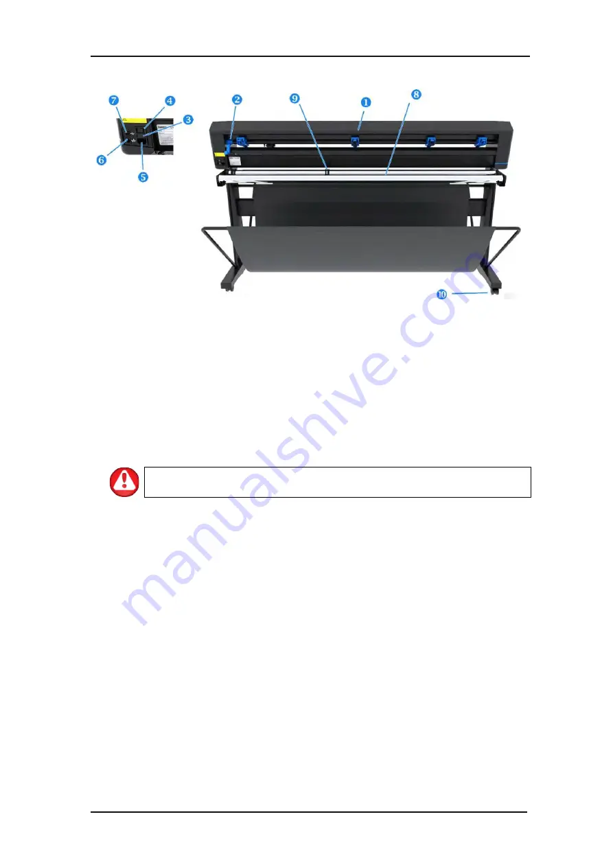
S ONE CUTTER REAR VIEW
1.
Pinch rollers:
The pinch rollers clamp the media to the drive system to ensure accurate
tracking. The D120 has one and the D140 and D160 have two extra pinch rollers to ensure
that wide media stays flat in the middle. The extra rollers in the middle can be enabled or
disabled.
2.
Pinch roller lever:
This lever is used to raise and lower the pinch rollers for media loading.
3.
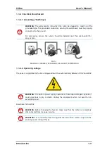
The fuse box:
The fuse is located at the right side of the power entry module. Check the
specification section to see which fuse is used in the S One cutter.
WARNING:
For continued protection against the risk of fire, replace only with
the same type and rating of the fuse.
4.
Power On/Off switch:
This rocker switch, situated in the middle of the power entry module,
sets the cutter’s power to ON or OFF. To switch on the power, press the “I” side of the
rocker switch. To switch off the power, press the “O” side of the rocker switch.
5.
AC power cord receptacle
: It is located on the left-hand side of the power entry module.
The power-up procedure is explained in detail in section 1.3. Always use a power cord
that was delivered with your cutter.
6.
USB port:
This interface is based on the standards specified in Universal Serial Bus
Specifications Revision 1.1. It allows high-speed bi-directional communication between
the host computer and the cutter.
7.
Ethernet port RJ45:
For connecting the cutter to the LAN.
8.
Media support rollers:
Rotating support rollers for the media roll.
9.
Roll media core holders:
The two core holders serve to keep the media roll in place when
media is pulled from the roll.
10.
Casters:
The casters on the stand are equipped with locking brakes. Once the cutter has
been moved to its new location, press the brakes with your foot to lock the casters.
1.2.2
The Cutter as viewed from the back

