Figures
6-1
6. FIGURES
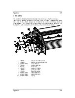
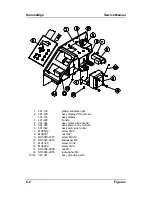
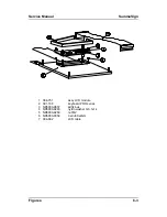
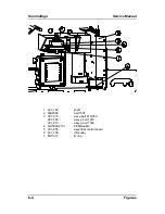
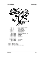
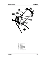
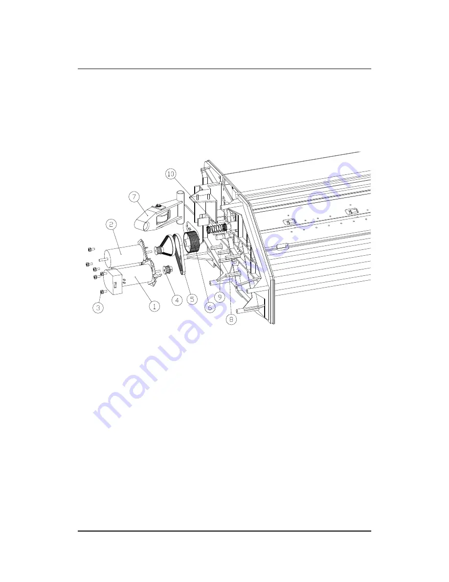
This section contains the detailed drawings of several assys of the SummaSign.
There are no detailed drawings of the base, since the base (containing baseplate
assys and the top beam assys) are considered as a whole and may never be
disassembled. If they should ever be taken apart (e.g. heavy transport damage), then
the base has to be reassembled in the factory or by a CalComp technician).
Figures
6-1
1
391-344
assy motor with encoder
2
391-809
assy motor without encoder
3
ND5000-9694
screw M4x10
4
391-198
setscrew
5
MB9124
belt 110T
6
391-152
421-567
pulley for 2 belts
pulley for 1 belt
7
421-165
assy idler pulley
8
ND5000-9643
standoff M4x40
9
ND5000-9683
standoff M4x30
10
ND5000-9769
spring
Summary of Contents for SummaSign D1010
Page 1: ...Service Manual SummaSign Series Summa NV Rochesterlaan 6 8470 Gistel Belgium...
Page 80: ...SummaSign Service Manual 106 107 2 36 Replacements Guidelines Blank page...
Page 85: ...Service Manual SummaSignT se 3 2 OPERATING VOLTAGE CONVERSION Maintenance and Cleaning 3 5...
Page 87: ...Service Manual SummaSignT se Maintenance and Cleaning 3 7 blank page...
Page 92: ...Service Manual SummaSign Calibration 4 5...
Page 93: ...SummaSign Service Manual HEAD CALIBRATION 4 6 Calibration...
Page 131: ...Service Manual SummaSign Spare Parts List 7 13...
Page 134: ...Summasign Service Manual 7 16 Spare Parts List...

