SummaSign
Service Manual
2.
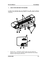
Parallel
Port : -
This
36-pin Centronics connector provides
a unidirectional
communication link between the cutter and a host computer. The cutter can
receive but not transmit data via this port.
Note : only one interface can be active at any one time.
The first port that receives data will be the active interface until the cutter is reset.
3.
Power ON/OFF switch
: - This rocker switch sets the cutter’s power to ON or
OFF. To switch the power ON, press the “I” side of the rocker switch. To switch
the power OFF, press the “O” side of the rocker switch.
4.
Power Entry Module : -
The fuse box, the voltage select board and the AC power
cord receptacle are located in the power entry module.
The power-up procedure is explained in detail in Section 1.6.
For information about the conversion of the cutter's operating voltage, see
Section 3.2.
5.
Roll Media Guide Bushes :
- The two guide bushes serve to keep the media roll
in place when media is pulled from the roll.
6.
Media Flanges
:
- The media flanges ensure proper routing of the media roll.
7.
Media Support Roller :
- Rotating support rollers for the media roll.
I-4
Introduction
Summary of Contents for SummaSign D1010
Page 1: ...Service Manual SummaSign Series Summa NV Rochesterlaan 6 8470 Gistel Belgium...
Page 80: ...SummaSign Service Manual 106 107 2 36 Replacements Guidelines Blank page...
Page 85: ...Service Manual SummaSignT se 3 2 OPERATING VOLTAGE CONVERSION Maintenance and Cleaning 3 5...
Page 87: ...Service Manual SummaSignT se Maintenance and Cleaning 3 7 blank page...
Page 92: ...Service Manual SummaSign Calibration 4 5...
Page 93: ...SummaSign Service Manual HEAD CALIBRATION 4 6 Calibration...
Page 131: ...Service Manual SummaSign Spare Parts List 7 13...
Page 134: ...Summasign Service Manual 7 16 Spare Parts List...


