background image

Service Manual

SummaSign

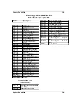
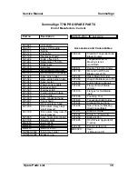
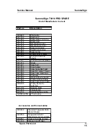
SummaSign T1010 PRO SPARE

End of Manufacture: Current

Part no

Description

390-643

Flat cable

391-168

Keyboard

391-286

Nameplate T1010 Pro

391-312

Roller assy

391-318

Media sensor rear

391-319

Media sensor front

391-326

Assy pinch roller

391-342

Switch pinch roller

391-344

Assy motor

391-346

Power entry module

391-366

Endcover right blk
plastic

391-367

Endcover left blk plastic

391-414

Drum

391-421

Assy belt

391-510

Core holder

391-600

Assy tangential head

391-655

Assy DC motor T head

391-664

Assy nose piece long

391-803

Fan assy

391-809

Motor without encoder

391-886

Cutting strip with tape

391-935

Assy final control board

398-198

Pulley 24 tooth +
setscrew

421-198

Bearing block

421-229

Transformer

423-155

Serial interface cable

ND5000-9769

Y belt spring


Accessories and Consumables

390-549

Standard Tangential Knife
Blade (Single)

390-550

Tangential knife for
Masking stencil (sandblast)

390-551

Double Tip Knife (single)

391-146

Manual Cut-Off razor

Spare Parts List

7-

15


Summary of Contents for SummaSign D1010

Page 1: ...Service Manual SummaSign Series Summa NV Rochesterlaan 6 8470 Gistel Belgium...

Page 2: ...Y 1 4 1 1 5 THE ENTER KEY 1 6 1 1 6 2 THE 1 AND 2 KEYS 1 6 1 1 7 THE JOGGING KEYS 1 6 1 1 8 THE TOOL UP DOWN KEY 1 6 1 1 9 THE TOOL SELECT KEY 1 7 1 2 NORMAL OPERATION 1 8 1 2 1 ON LINE AND OFF LINE 1...

Page 3: ...4 3 EMULATE 1 14 1 4 4 TOOL 1 15 1 4 5 MENU UNITS 1 15 1 4 6 ADDRESSING 1 15 1 4 7 BAUD RATE 1 15 1 4 8 PARITY 1 16 1 4 9 RTS DTR 1 16 1 4 10 DM PL ERRORS 1 17 1 4 11 HP GL ERRORS 1 17 1 4 12 HP GL O...

Page 4: ...UST LONG TEST ROUTINE 1 25 1 5 5 CUT BORDER 1 26 1 5 6 MENU PLOT 1 26 1 5 7 CONFIDENCE CUT 1 27 1 5 8 DIN CUT 1 27 1 5 9 SYSTEM TESTS 1 27 1 6 SYSTEM TESTS 1 28 1 6 1 LANGUAGE 1 28 1 6 2 ROM REVISION...

Page 5: ...AND THE OLD 750 7 2 6 REPLACING AN X MOTOR IN THE MODELS 750 1010 AND 1300 9 2 7 REPLACING THE Y MOTOR 11 2 8 REPLACING THE LCD OR THE KEYBOARD 13 2 9 REPLACING THE MAIN PCB 15 2 10 REPLACING THE SMAL...

Page 6: ...ON 4 CALIBRATION 4 1 MACHINE TYPE 4 2 4 2 MEDIA CALIBRATION 4 4 4 3 HEAD CALIBRATION 4 5 I KNIFE CALIBRATION TANGENTIAL 4 5 II COIL CALIBRATION 4 5 4 5 OPOS CALIBRATION OPTIONAL 4 8 I NORMAL CALIBRATI...

Page 7: ...D MESSAGES 5 5 5 10 RS232 ERROR 5 6 5 11 INTERNAL ERRORS 5 6 5 12 FLASHING ERRORS AND MESSAGES ONLY ON NEW TYPE OF PCB 5 7 5 13 ROM ERROR 5 7 5 14 RAM ERROR 5 7 5 15 MACHINE UNABLE TO FIND THE KNIFE H...

Page 8: ...ASIGN D610 SPARE PARTS 7 2 SUMMASIGN D610 PRO SPARE PARTS 7 3 SUMMASIGN T610 SPARE PARTS 7 4 SUMMASIGN T610 PRO SPARE PARTS 7 5 SUMMASIGN D750 SPARE PARTS 7 6 SUMMASIGN D750 PRO SPARE PARTS 7 7 SUMMAS...

Page 9: ...UMMASIGN D1300 PRO SPARE PARTS 7 16 SUMMASIGN T1300 SPARE PARTS 7 17 SUMMASIGN T1300 PRO SPARE PARTS 7 18 Appendix A removal of the left side Appendix B procedure to flash from internal ROM s Appendix...

Page 10: ...serves the right to change any information contained in this manual without prior notice Unauthorised copying modification distribution or display is prohibited All rights reserved 2 MANUAL ORGANIZATI...

Page 11: ...e following An overview of the maintenance of various parts of the unit It is advisable to carefully read the procedure described in each of the chapters prior to removing or replacing a particular pa...

Page 12: ...ead the following description of the rear panel components Figure 1 1 shows the location of the main components 1 RS 232 C Port This DB 9P connector provides the communication link between the cutter...

Page 13: ...ON press the I side of the rocker switch To switch the power OFF press the O side of the rocker switch 4 Power Entry Module The fuse box the voltage select board and the AC power cord receptacle are l...

Page 14: ...edia Drive Sleeves The media drive sleeves move the media only when the pinch rollers are in the down position The following table lists the number of media drive sleeves installed on each model of th...

Page 15: ...d between the rubber rollers and the media drive sleeves The T1010 and T1300 units are provided with an extra low pressure roller in the middle to keep the vinyl media flat 8 Cutting strip Soft strip...

Page 16: ...the liquid crystal display LCD and the control panel keys are explained in the following paragraphs The explanation has been written for a T series cutter The only difference with the D series is tha...

Page 17: ...ut in progress or to recut the last file When the key RESET LOAD is pressed the cutter goes off line suspends all operations in progress and displays the RESET LOAD menu Press the key until SET ORIGIN...

Page 18: ...or jogging key to make the media move forward towards you or backward away from you Moving the media forward will prove to be very practical when you require to cut the finished sign off manually Pres...

Page 19: ...ptions press the jogging key To exit from the menus and resume the previous on line operation press the key ON LINE Under normal conditions the cutter is on line it may then be selected by the host co...

Page 20: ...s their use is displayed on the LCD as appropriate THE JOGGING KEYS The use of the jogging keys varies according to the operation in progress For example when working in the USER CONFIG menu the or jo...

Page 21: ...he key then press the or jogging key until the desired tool appears on the second line o the LCD Press the key to confirm the tool An asterisk appears next to the selected tool When the cutter is powe...

Page 22: ...umber In all other cases the cutter is off line When on line the cutter can be addressed by the host computer which means that the cutter will execute cutting or plotting instructions issued by the ho...

Page 23: ...cutting plotting operation until the cutter is put on line again LOCAL OPERATION Local operation is only possible while the cutter is off line Local operation means that the cutter is operated directl...

Page 24: ...2 Press the key until USER CONFIG 1 4 is displayed 3 Press the or jogging key until the desired configuration number is dis played next to USER CONFIG NOTE Before altering any of the items in the USE...

Page 25: ...SummaSign series Cutters Service Manual IN DM PL ONLY IN HP GL AND HP GL 2 ONLY FLOWCHART SHOWING FACTORY PRESET MENU SETTINGS 1 10 Keyboardcontrols...

Page 26: ...dify the pressure of the pouncing tool The default pouncing pressure value is 120 grams The pressure can be set between 0 and 600 grams in 5 gram increments On the LCD the active pouncing pressure val...

Page 27: ...ity can be set between 50 mm s 2 ips and 1000 mm s 40 ips OVERCUT The OVERCUT submenu enables you to generate an overcut in order to facilitate weeding the cut The default overcut is set to 1 The over...

Page 28: ...LCD the active plotting language setting is marked with an NOTE The active cutting plotting language MUST match the cutting software Always select a language which is supported by the host computer s...

Page 29: ...GL 2 the addressing is fixed at 0 025 mm The default addressing resolution is 0 025 mm Europe or 0 001 US The user addressable resolution can be set to 0 025 mm or 0 001 or 0 1 mm or 0 005 On the LCD...

Page 30: ...tting is marked with an NOTE The parity setting of your cutter MUST match the host computer s parity setting RTS DTR The RTS DTR submenu controls the Request To Send RTS and Data Terminal Ready DTR si...

Page 31: ...ly be displayed if PLOT LANGUAGE is set to HP GL The HP GL ERRORS submenu can be set to REPORTED or IGNORED On the LCD the active setting is marked with an The feature is activated by selecting REPORT...

Page 32: ...the P and SP commands respectively are ignored or accepted When the TOOL COMMAND option is set to ACCEPT the P or SP commands will change the selected tool in the cutter according to the suffix that...

Page 33: ...ll activate the configuration menu which allows you to set the cutting pressure and the cut length 1 CUT LENGTH This parameter determines the length that is cut with full pressure By pressing the 1 ke...

Page 34: ...or a pen 4 Press the key until INTERNAL TEST is displayed and press the jogging key 5 Press the or jogging key until the desired internal test is displayed 6 To perform the test press the key To exit...

Page 35: ...alibration routine the cutter will cut a series of test patterns which will allow you to identify errors in knife rotation and concentricity Corrective measures can be taken using the control panel ke...

Page 36: ...centre of the knife Theoretical 0 angle of the knife ORIGIN deviation POSSIBLE KNIFE CALIBRATION GROUNDS The calibration settings entered during the knife calibration routine are automatically stored...

Page 37: ...rn increase the value displayed on the LCD by pressing the jogging key to correct closing of the circles cut To repeat the test press the key Press the key to go to the next step of the calibration pr...

Page 38: ...s from the centre to the horizontal line at the bottom Carefully check the alignment of the different cuts the two vertical lines should meet seamlessly precisely in the middle without any gaps Weed o...

Page 39: ...All the squares should be identical Press the key to go to the next step of the procedure ADJUST LONG test routine ADJUST LONG 0 1 Press to execute the LONG test The test pattern is similar to the LA...

Page 40: ...ne the LONG adjustment Press the 1 key to perform the horizontal test all the squares should be identical CUT BORDER The CUT BORDER submenu is used to cut the border of the media area which was define...

Page 41: ...UT also performs an electrical and mechanical test of the cutter in order to check the cut quality but also provides the user with feedback on knife setting knife pressure knife offset and cutting dep...

Page 42: ...nglish French German Dutch Spanish or Italian ROM REVISION Selecting the ROM REVISION option by pressing the key will furnish the details on the cutter s ROM revision This information is often helpful...

Page 43: ...alified service personnel RS232 TEST The RS232 TEST routine verifies the cutter s RS 232 C serial communications transmit data receive data and hardware handshaking circuits This test does not require...

Page 44: ...and pen landing After adjustment the value is saved in the system s non volatile RAM To execute this test a tension gauge of 100 gr and 500 gr is required In the upper line of the display the desired...

Page 45: ...the unit has been assembled on a fixture to assure straightness all along the y axis To keep this DO NOT REMOVE THE SIDE PLATES NOR THE Y GUIDING Unplug the line cords and host cables before transport...

Page 46: ...SummaSign Service Manual 2 2 Replacements Guidelines 1 body 2 left end cover 391 367 3 right end cover 391 366 4 long screws rozet MH868 ND5000 9639 2x4x 5 short screw rozet MH595 ND5000 9639 2x1x...

Page 47: ...ight hand cover in place Three are located at the front one at the rear and one at the bottom it is not necessary to turn the unit upside down to remove the bottom screw Caution The rear screw is loca...

Page 48: ...SummaSign Service Manual 2 4 Replacements Guidelines 1 body 2 bottom plate 3 screws depends on type of machine 4 slot for bottom plate 1 camroller assy 2 camroller 3 camrollershaft 4 setcrew...

Page 49: ...ed correctly into the slot of the front plate and the rear plate 9 10 REPLACING THE CAM ROLLERS To replace the cam rollers proceed as follows 13 Remove the set screw on either side of the cam rollers...

Page 50: ...SummaSign Service Manual 2 6 Replacements Guidelines 1 body 2 motor with encoder 3 screws 4 belt 1 motor 2 capacitor 3 connector encoder WATCH ORIENTATION 4 wires motor...

Page 51: ...r To re install proceed in the reverse order of removal Make sure to firmly tighten all screws 16 Note 17 When re installing 18 a Make sure the wire of the connector attached to the encoder runs outwa...

Page 52: ...Replacements Guidelines 1 motor with encoder 2 motor without encoder 3 gap between belts 1 body 2 motor with encoder 3 motor without encoder 4 screw 5 belt 1 motor 2 capacitor 3 connector encoder WAT...

Page 53: ...lder the black wire to the minus entry and the red wire to the plus entry The and signs are located in the corners of the motor s label 25 c Be extremely careful to plug the connector into the correct...

Page 54: ...SummaSign Service Manual 2 10 Replacements Guidelines 1 body 2 y motor 3 screw 3x 1 motor 2 capacitor 3 connector encoder WATCH ORIENTATION 4 wires motor...

Page 55: ...erse order of removal Make sure to firmly tighten all screws 29 Note 30 When re installing 31 a Make sure the wire of the connector attached to the encoder runs outward 32 b Make sure to solder the bl...

Page 56: ...SummaSign Service Manual 2 12 Replacements Guidelines 1 body 2 keyboard assy 3 nut 4 lockwasher 5 grounding wire 1 LCD assy 2 keyboard 3 spacer 4 washer 5 nut M2 6 dust cover 7 LCD cable...

Page 57: ...the connector and pull the flat cable loose it sticks to the other flat cables 35 Pull the flat cable for the keyboard off the PCB 36 Pull the flat cable for the LCD off the PCB 37 Remove the four sc...

Page 58: ...ctor y encoder 6 place for safeguard 2d connector x encoder 7 grounding clamps 2e connector main power 8a completely unscrew this one 2f connector y motor 8b just loosen this one a bit 2g connector x...

Page 59: ...95 To replace a PCB proceed as follows 42 Remove the right hand cover see Chapter 2 2 Removing the right hand cover At the top of the PCB 43 44 Disconnect the various connectors Pay close attention to...

Page 60: ...ctor y encoder 6 place for safeguard 2d connector x encoder 7 grounding clamps 2e connector main power 8a completely unscrew this one 2f connector y motor 8b just loosen this one a bit 2g connector x...

Page 61: ...plug the connectors into the correct holes 44 See the drawing in section 7 for the exact positioning of the connectors The drawing shows the PCB of a new model Type 2 The old model Type 1 differs on t...

Page 62: ...SummaSign Service Manual 2 18 Replacements Guidelines 1 main pcb 2 small pcb 3 cover plate 4 screws 5 hex nuts...

Page 63: ...de of the serial port 60 Remove the cover 61 Remove the two screws holding the small PCB in place 62 Remove the screw or the two screws on the right hand side that hold the drivers against the small P...

Page 64: ...SummaSign Service Manual 2 20 Replacements Guidelines 1 cover head 2 head 3 screws cover head 4 position screws to hold head 5 flatcable...

Page 65: ...le out of the connector 68 Remove the drag head To do this loosen the three screws with two counterclockwise rotations using a small diameter screw driver and lift the head upwards to remove it from t...

Page 66: ...SummaSign Service Manual 2 22 Replacements Guidelines 1 cover head 2 head 3 screws cover head 4 position screws to hold head 5 flatcable...

Page 67: ...st the mounting of the head 79 80 Firmly tighten the screws once the drag head is properly positioned 81 Put the flat cable back into the connector and close the connector To ensure good contact the f...

Page 68: ...SummaSign Service Manual 61 62 2 24 Replacements Guidelines 1 body 2 flatcable path 3 loop may not touch anything when head is completely on the left...

Page 69: ...PCB by pulling the flat cable connector cover up On both sides of the connector cover there is a small protuberance that you can pry up using a screwdriver Gently pull the flat cable out of the conne...

Page 70: ...ual 2 26 Replacements Guidelines 1 additional strip 2 glued for about 2cm 3 flatcable 1 flatcable 2 this edge is 110mm 3 screw to hold flatcable holder 4 screws to hold flatcable clamp 5 flatcable hol...

Page 71: ...long the length of the unit 70 Caution 71 Make sure the loop is neither too long nor too short A very long loop may get caught behind other parts and break A very short loop may break as the head move...

Page 72: ...SummaSign Service Manual 2 28 Replacements Guidelines 1 Strip Pur 2 unscrew the one closest to the head...

Page 73: ...with a springload system the belt tension need not be adjusted 123 REPLACING THE CUTTING STRIP To replace the cutting strip proceed as follows 124 Loosen the cutting strip on the left hand or right h...

Page 74: ...SummaSign Service Manual 130 2 30 Replacements Guidelines 1 body 2 fan 3 fan guard 4 screws washers 5 front sensor 6 rear sensor...

Page 75: ...should be returned to their original location when re installed 135 Disconnect the other end of the sensor wire from the PCB 136 Remove the sensors To re install proceed in the reverse order of remov...

Page 76: ...2 32 Replacements Guidelines 1 body 2 drum 3 screws depending on the type 4 pulley 5 see remark in text det1 push all the bearing blocks in the same direction det2 equal distances det3 push the pillow...

Page 77: ...ive drum 92 Note 93 Because all the sleeves of the drive drum are accurately matched it is not possible to replace just one sleeve To re install proceed as follows 156 Put the drum into the shaft in t...

Page 78: ...2 34 Replacements Guidelines 1 body 2 drum 3 screws depending on the type 4 pulley 5 see remark in text det1 push all the bearing blocks in the same direction det2 equal distances det3 push the pillo...

Page 79: ...rse order of removal Make sure to firmly tighten all screws 171 100 Caution 101 Make sure the sensor wire does not touch the drive drum The rotating drum may damage the wire and cause malfunctioning 1...

Page 80: ...SummaSign Service Manual 106 107 2 36 Replacements Guidelines Blank page...

Page 81: ...are virtually friction free and require no lubrication They will however collect dust and lint which may affect the performance of the cutter Keep the cutter as clean as possible by using a dust cove...

Page 82: ...ocal operation will allow you to use the control panel jogging keys even when no media is loaded 3 Remove the backing from a piece of vinyl Place the vinyl with the tacky side down between one of the...

Page 83: ...malfunctioning of the cutter To clean the sensor area proceed as follows 1 The sensors are located on the cutter s right side One sensor is located on the front platen the other sensor is located on...

Page 84: ...oceed as follows 1 Gently take out the knife or ball point pen by turning the knife holder anticlockwise 2 Observe the orientation of the nose piece first and then push it out of its holder 3 Remove a...

Page 85: ...Service Manual SummaSignT se 3 2 OPERATING VOLTAGE CONVERSION Maintenance and Cleaning 3 5...

Page 86: ...he fuses as appropriate to the voltage To change the fuse s remove the fuse s from the fuse box behind the cover plate of the power entry module For 100 or 120 V AC operation of cutters with 1 x motor...

Page 87: ...Service Manual SummaSignT se Maintenance and Cleaning 3 7 blank page...

Page 88: ...General This section contains information on the calibration of replaced parts and on the recalibration of worn down parts Each time a unit is serviced check this section to see which calibration has...

Page 89: ...f you select Special init the default values are put into the NVRAM It is advisable to use Special init if the unit does not start with Standard init or if the unit is completely disordered 3 Caution...

Page 90: ...IDELINES TO THE LETTER YOU CAN INFLICT SERIOUS DAMAGE BEYOND REPAIR TO THE MACHINE IF THE WRONG PARAMETERS ARE CHANGED 3 Select Setup machine in the list of system tests and choose the correct model t...

Page 91: ...high accuracy is needed the unit has to be recalibrated when different thicknesses of material are used However recalibrating is not needed for normal usage Calibration Load media in the machine the...

Page 92: ...Service Manual SummaSign Calibration 4 5...

Page 93: ...SummaSign Service Manual HEAD CALIBRATION 4 6 Calibration...

Page 94: ...pressure is displayed and the bottom line shows the value that has to be sent to the head to reach the pressure displayed Press the key The following message is displayed on the LCD 600 g PRESSURE 11...

Page 95: ...the key to adjust the ball point pen landing pressure The following message will be displayed PEN LANDING 14 Press the key repeatedly until the ball point pen moves upwards value around 2 Press the k...

Page 96: ...Service Manual SummaSign NOTE For a good cutting quality the landing values must be at least 3 less then the 40g pressure Calibration 4 9...

Page 97: ...To calibrate the optical system proceed as follows 1 Power up the unit and load a piece of black vinyl with a white backing The load procedure is described in section 1 2 Set the origin on a clean bla...

Page 98: ...Service Manual SummaSign PRESS MENU Weed carefully with tweezers the rectangle cut and press the key The cutter will now measure the rectangle and set its calibration parameters Calibration 4 11...

Page 99: ...her than 300 Then turn CW until the value doesn t decrease anymore and turn 1 8 of a turn CCW Place the sensor above a glossy piece of black material Turn the left pot meter CCW until the display does...

Page 100: ...st follow the guidelines on the LCD screen is shown when the sensor is covered is shown when the sensor is uncovered The bottom arrow has to be at least 2 positions further than the top arrow for the...

Page 101: ...ION 5 Troubleshooting Error codes General This section contains information on the error codes which can appear on the LCD screen A step by step procedure is provided in this section to prevent this e...

Page 102: ...AXIS Cause The drum motor cannot move to the required position This is a fatal error It can only be solved by turning the power off and then on again This error is usually caused by a media crash in t...

Page 103: ...the machine will give this error This is a fatal error Switching the power off and making a corrective action is the only solution Action 20 Measure the line voltage Check whether the voltage selector...

Page 104: ...Cause For DMPL when a wrong set of instruction is sent to the machine This message only appears when the machine is configured to report DMPL ERRORS Action 32 Set DM PL ERRORS to IGNORED in the MENU t...

Page 105: ...SER NVRAM HAS BEEN DEFAULTED DUE TO ROM CHANGE Action 44 Message appears when rebooting the machine for the first time after an upgrade of the ROM s The configuration of the machine will be defaulted...

Page 106: ...area on the PCB 53 Replace the main PCB 54 55 INTERNAL ERRORS Cause Happens when there is a Firmware problem or a problem with the main board address bus or data bus the following list gives an overv...

Page 107: ...LASH CORRUPTED UPGRADE FILE Action 64 Those are fatal errors The information in the internal ROM s is not reliable any more 65 Order ROM s and do an internal reflash 66 Change main PCB 67 68 ROM ERROR...

Page 108: ...ad to the PCB 78 Replace the main PCB 79 MARKERS NOT SENSED PROPERLY Cause The machine has trouble during its special load sequence Action 80 Check whether there is dust on the sensor tip 81 Make sure...

Page 109: ...led If they should ever be taken apart e g heavy transport damage then the base has to be reassembled in the factory or by a CalComp technician Figures 6 1 1 391 344 assy motor with encoder 2 391 809...

Page 110: ...29 transfo 4 391 344 assy motor with encoder 5 391 346 assy power entry module 6 391 342 assy switc pinch roller 7 MH0598 screw 6 32 8 MH0071 nut 6 32 9 ND5000 9175 screw M2x10 10 ND5000 9276 flatwash...

Page 111: ...ual SummaSign Figures 6 3 1 384 751 assy LCD module 2 391 168 keyboard PRO series 3 ND5000 9657 skiffy bus 4 ND5000 9283 nylon washer 7x3 1x1 4 5 ND5000 9269 nut M2 6 ND5000 9358 Celrub 9x2mm 7 384 68...

Page 112: ...6 4 Figures 1 421 140 shaft 2 MB0380 belt 150T 3 391 315 391 555 391 813 ass y belt 610 750 assy y belt 1010 assy y belt 1300 4 ND5000 9151 PEMstud M3 5 391 935 assy final control board 6 421 139 dbl...

Page 113: ...91 182 flatcable clamp 6 ND5000 9667 ND5000 9668 screw M2x4 model 610 750 screw M2x5 model 1010 1300 7 ND5000 9267 flatwasher M2 8 ND5000 9540 hexnut M4 9 ND5000 9231 lockwasher M4 10 ND5000 9620 wash...

Page 114: ...ssy wire encoder 16 391 628 motor bracket 17 391 661 magnet assy 1 391 201 assy up down 2 391 206 assy up down support 3 391 209 magnet assy 4 391 213 bus mount assy 5 391 216 pcb drag head 6 391 215...

Page 115: ...391 410 391 187 bottom plate 610 750 bottom plate 1010 bottom plate 1300 5 391 320 391 803 fan assy 610 750 fan assy 1010 1300 6 MF0067 guard fan 7 ND5000 9315 flatwasher M4 8 ND5000 9606 screw M4x45...

Page 116: ...34 washer 8 2x25x2 5 3 391 130 distance bus 8x13x3 4 ND5000 9633 lockwasher M8 5 ND5000 9632 screw M8x16 6 ND5000 9499 corex cap 7 ND5000 9631 screw M8x16 DIN 912 8 391 183 brake 9 391 171 roller guid...

Page 117: ...Service Manual SummaSign Figures 6 9 1 motor encoder 2 red on 3 black on 4 connector 5pin 5 tie wrap holder 6 tie wrap 7 capacitor MC1697...

Page 118: ...40 connecting pin 5 ND5000 9621 setscrew M3x12 6 ND5000 9607 truarc dia 4 7 390 142 shaft camroller 8 ND5000 9196 setscrew M3x5 9 391 326 assy pinch roller 10 ND5000 9244 spring plunger dia 4 11 391 1...

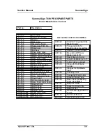
Page 119: ...roller 391 342 Assy switch pinch roller 391 344 Assy motor 391 346 Assy power entry module 391 386 Cutting strip with tape 391 463 Keyboard 391 510 Set of core holder 391 553 Drum 391 555 Belt assy 39...

Page 120: ...try module 391 366 Endcover right 391 367 Endcover left 391 386 Cutting strip with tape 391 510 Set of Core holders 391 935 Assy final control board MB0380 Belt 150T80 MB9124 Belt 110T80 MW9987 Rom U2...

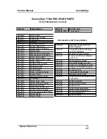
Page 121: ...Power entry module 391 366 Endcover right 391 367 Endcover left 391 386 Cutting strip with tape 391 510 Core holders 391 935 Assy final control board MB0380 Belt 150T80 MB9124 Belt 110T80 ND5000 9622...

Page 122: ...sy final control board 421 198 Bearing block MB0380 Belt 150T80 MB9124 Belt 110T80 MB9125 Belt 63T 2mm ND5000 9622 Knob core holder ND5000 9698 Brake O ring Accessories and Consumables 390 549 Standar...

Page 123: ...l board 421 198 Bearing block MB0380 Belt 150T80 MB9124 Belt 110T80 MB9125 Belt 63T 2mm ND5000 9622 Knob core holder ND5000 9698 Brake O ring ND5000 9769 Y belt spring Accessories and Consumables 390...

Page 124: ...cover right 391 367 Endcover left 391 386 Cutting strip with tape 391 510 Set of Core holders 391 705 Drive drum Assy 391 935 Assy final control board MB0380 Belt 150T80 MB9124 Belt 110T80 MW9987 Rom...

Page 125: ...left 391 386 Cutting strip with tape 391 510 Core holders 391 705 Drive drum Assy old 4 small sleeves 391 735 Drive drum Assy new 5 small sleeves 391 935 Assy final control board MB0380 Belt 150T80 M...

Page 126: ...sy final control board 421 198 Bearing block MB0380 Belt 150T80 MB9124 Belt 110T80 MB9125 Belt 63T 2mm ND5000 9622 Knob core holder ND5000 9698 Brake O ring Accessories and Consumables 390 549 Standar...

Page 127: ...5 small sleeves 391 935 Assy final control board 421 198 Bearing block MB0380 Belt 150T80 MB9124 Belt 110T80 MB9125 Belt 63T 2mm ND5000 9622 Knob core holder ND5000 9698 Brake O ring ND5000 9769 Y be...

Page 128: ...391 510 Set of Core holders 391 803 Fan assy 391 809 Assy motor without encoder 391 886 Cutting strip with tape 391 935 Assy final control board 398 198 Pulley 24 tooth setscrew MB0380 Belt 150T80 MB9...

Page 129: ...Drive drum Assy 391 421 Belt assy 391 510 Core holders 391 803 Fan assy 391 886 Cutting strip with tape 391 935 Assy final control board MB0380 Belt 150T80 MB9124 Belt 110T80 ND5000 9622 Knob corehold...

Page 130: ...sy final control board 421 198 Bearing block MB0380 Belt 150T80 MB9124 Belt 110T80 MB9125 Belt 63T 2mm ND5000 9622 Knob core holder ND5000 9698 Brake O ring Accessories and Consumables 390 549 Standar...

Page 131: ...Service Manual SummaSign Spare Parts List 7 13...

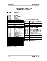
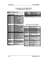
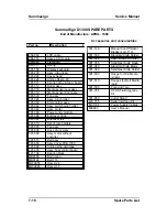
Page 132: ...ntroller board 398 198 Pulley 24 tooth setscrew 423 155 Serial interface cable MB0380 Belt 150T80 MB9121 Bearing MB9129 Belt 140T80 MB9130 Belt 370T MW9987 EPROM lo MW9988 EPROM hi ND5000 9702 Spring...

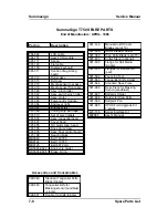
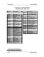
Page 133: ...stic 391 414 Drum 391 421 Assy belt 391 510 Core holder 391 600 Assy tangential head 391 655 Assy DC motor T head 391 664 Assy nose piece long 391 803 Fan assy 391 809 Motor without encoder 391 886 Cu...

Page 134: ...Summasign Service Manual 7 16 Spare Parts List...

Page 135: ...r Roll Media pair 391 596 Pouncing Tool 391 663 Tangential Knife Holder 391 664 Standard Nose Piece 391 666 Nose Piece for Masking Stencil sandblast 391 667 Ballpoint Holder 391 668 Holder for Drag Kn...

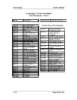
Page 136: ...left 391 510 Set of core holders 391 803 Fan assy 391 804 Drive drum Assy 391 809 Assy motor without encoder 391 813 Belt assy 391 860 Assy driver PCB 1300 391 886 Cutting strip with tape 391 935 Assy...

Page 137: ...ight 391 367 Endcover left 391 510 Core holder 391 803 Fan assy 391 804 Drive drum Assy 391 809 Assy motor without encoder 391 813 Belt assy 391 860 Assy driver PCB 1300 391 886 Cutting strip with tap...

Page 138: ...0 Assy driver PCB 1300 391 886 Cutting strip with tape 391 935 Final control board T1300 MB0380 Belt 150T80 MB9124 Belt 110T80 MB9125 Belt 63T 2mm MW9987 Rom U24 MW9988 Rom U17 Accessories and Consuma...

Page 139: ...ssy D1300 391 860 Assy driver PCB 1300 391 886 Cutting strip with tape 391 935 Final control board T1300 MB0380 Belt 150T80 MB9124 Belt 110T80 MB9125 Belt 63T 2mm ND5000 9769 Y belt spring Accessories...

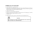
Page 140: ...m screw Pay close attention to where each of the screws goes They should be returned to their original location when re installed 2 Gently tap the top of the cover 3 Remove the cover fig1 fig1 4 Unscr...

Page 141: ...inal location when re installed 2 Gently tap the top of the cover 3 Be careful not to tear the flatcable off the keyboard 4 Remove the connector Play close attention to where the connector of the flat...

Page 142: ...om s Procedure 1 Do all the necessary stuff to expose the main PCB make sure the unit is not powered on 2 Put in MW9955 and MW9965 in LO and HI are marked on the PCB 3 Put jumpers next to the ROM s on...

Page 143: ...Put it on a steady and flat table 1 Open the camrollers and leave the lever in that position until the top cover is back on the machine 2 Remove the left and right cover 2 times 5 screws 3 Remove the...

Page 144: ...ges and has to be removed if there is a defect with the right camroller 21 Remove and replace the faulty components 3 If a Ccamroller assy is replaced make sure the plastic cam inside the assy is 4 po...

Page 145: ...top beam and base plate or call for help 17 tracking test 18 Do a couple of tracking test preferably over 6m or more to ensure the tracking 19 quality 20 If it fails the test then following action mi...

Page 146: ...unit whilst pressing on PEN_UPDOWN ONE and ENTER FSM mode This brings the unit in a special mode from now on anything can go wrong If the display shows FSM MODE STANDARD INIT Then press ENTER Note If...

Page 147: ...7 Power the unit back on and check whether the flashed PCB works 8 Put everything back you ve disassembled Internal Reflash B 2...

Page 148: ...oller bar it 10 and the lever with one hand loosen the other setscrew in the lever 7 Turn the pinchroller bar away from you whilst pushing it to the right then turn it 3 degrees back 8 Tighten the set...

Page 149: ...Lever play C 2 1 cam detection ring 6 bus 8 2 12 15 2 spring 7 lever pinch roller 3 screw M4x10 8 starlock 8 4 screw M4x12 9 washer 08x8x10 5 washer 08x8x10 10 pinch roller bar...

Page 150: ...e of the machine 8 start the machine in FSM mode standard 9 press the menu key until you come to internal test 10 press the up arrow until you get to knife calibration 11 press enter 10 press 2 this w...

Page 151: ...hanging the motor on a T head D 2 1 motor assy 2 motor pulley 3 setscrew on motor pulley 4 check belt tension 5 disconnect encoder here 6 disconnect motor here 7 hex screws 8 holes facing rear of head...

Reviews: