Replacements Guidelines
2-1
SECTION 2
Replacements guidelines
General
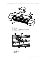
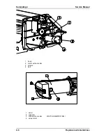
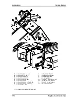
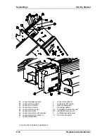
This section contains information on replacing defective parts and adjustment procedures. A step-by-
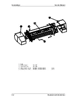
step removal/assembly procedure is provided in this section. On the left page you will find drawings
indicating the position of the parts. Use the last section of this manual for detailed assembly pictures.
Precautions
Observe simple, common sense rules and procedures whilst servicing the unit. They include, but are
not limited to the following:
1.
The base of the unit has been assembled on a fixture to assure straightness all along the y-axis.
To keep this :
DO NOT REMOVE THE SIDE PLATES NOR THE Y-GUIDING.
Unplug the line cords and host cables before transporting the unit to other places.
Reassemble ALL parts (screws, ferrite shield, etc.) to maintain EMI integrity, and guide the loose
wires afterwards with tie-wrap in the same manner they were before
Watch for sharp edges on the metal strips etc.
When the covers are off or open:
The printed circuits boards are electrostatically sensitive; use the proper handling
techniques.
Keep sensors and reflection plates free of scratches and dirt.
Keep the guiding, at least dirtfree where the wheels of the carriage pass.
Replacements Guidelines
2-1
Summary of Contents for SummaSign D1010
Page 1: ...Service Manual SummaSign Series Summa NV Rochesterlaan 6 8470 Gistel Belgium...
Page 80: ...SummaSign Service Manual 106 107 2 36 Replacements Guidelines Blank page...
Page 85: ...Service Manual SummaSignT se 3 2 OPERATING VOLTAGE CONVERSION Maintenance and Cleaning 3 5...
Page 87: ...Service Manual SummaSignT se Maintenance and Cleaning 3 7 blank page...
Page 92: ...Service Manual SummaSign Calibration 4 5...
Page 93: ...SummaSign Service Manual HEAD CALIBRATION 4 6 Calibration...
Page 131: ...Service Manual SummaSign Spare Parts List 7 13...
Page 134: ...Summasign Service Manual 7 16 Spare Parts List...

