Service Manual
SummaSign
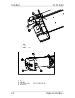
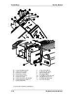
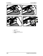
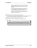
Apart from the standard adjustment tools used in the standard
operating procedure, you can use an ordinary 3½" disk to
adjust the height and position of the head. To do this, proceed
as follows:
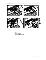
a. Put the disk against the drag head (the same way as you
would put an adjustment plate against it) to verify that the drag
head is positioned perpendicularly to the cutting surface.
b. Slide the disk under the knife holder. If the disk touches the
knife holder this means that the head is mounted too low.
Readjust the mounting of the head.
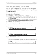
79.
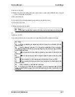
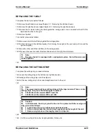
80.Firmly tighten the screws once the drag head is properly positioned.
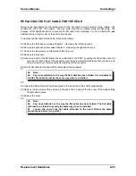
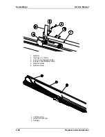
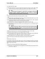
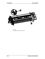
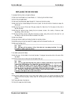
81.Put the flat cable back into the connector and close the connector. To ensure good contact, the flat
cable must be positioned as deeply as possible and in the middle of the connector.
82.Remount the front cover of the head and firmly tighten the screws.
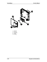
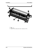
83.Proceed in the reverse order of removal. Make sure to firmly tighten all screws.
84.
57.
Note:
58.
Now that you have replaced the head, it is extremely important that you bring
the data stored on the PCB in line with the head and vice versa. See Chapter 11,
Configuration of the head or the PCB for detailed information on how to do this.
59.
60.
Replacement Guidelines
2-23
Summary of Contents for SummaSign D1010
Page 1: ...Service Manual SummaSign Series Summa NV Rochesterlaan 6 8470 Gistel Belgium...
Page 80: ...SummaSign Service Manual 106 107 2 36 Replacements Guidelines Blank page...
Page 85: ...Service Manual SummaSignT se 3 2 OPERATING VOLTAGE CONVERSION Maintenance and Cleaning 3 5...
Page 87: ...Service Manual SummaSignT se Maintenance and Cleaning 3 7 blank page...
Page 92: ...Service Manual SummaSign Calibration 4 5...
Page 93: ...SummaSign Service Manual HEAD CALIBRATION 4 6 Calibration...
Page 131: ...Service Manual SummaSign Spare Parts List 7 13...
Page 134: ...Summasign Service Manual 7 16 Spare Parts List...


