


SummaSign Pro SL D-series Cutters
User’s Manual
General Information
1-22
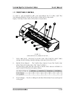
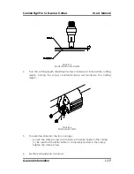
over the sleeves in order to ensure proper media traction. It is very important
that the left and right edges of the media always rest on sleeves. Position the
pinch rollers so that they are 3 to 15 mm (0.1" to 0.6") in from the edge of the
media.
On the D1010 Pro SL, D1400 Pro SL, and D1600 Pro SL cutters, two, three or more
sleeves may be partly or fully covered, depending on the media width used. To
ensure correct positioning of the pinch rollers, reference marks in the shape of
inverted triangles have been provided on the head guide.
The center low-pressure roller is used to enhance media routing and keep the
vinyl flat. Ideally, this roller should be positioned halfway between the two edge
rollers but always over one of the drive sleeves.
The center low-pressure roller(s) can be in the raised position on the D1010 Pro
SL, D1400 Pro SL, and D1600 Pro SL cutters when media narrower than 600 mm is
being cut.
1.8.2
FEEDING AND POSITIONING MEDIA
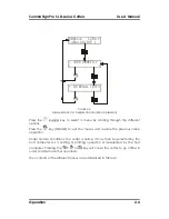
The following load procedure has been found to be very reliable. Adhere to
these step-by-step instructions when loading media.
Î
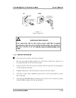
To load media, proceed as follows:
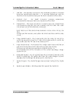
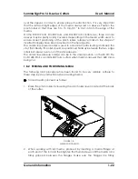
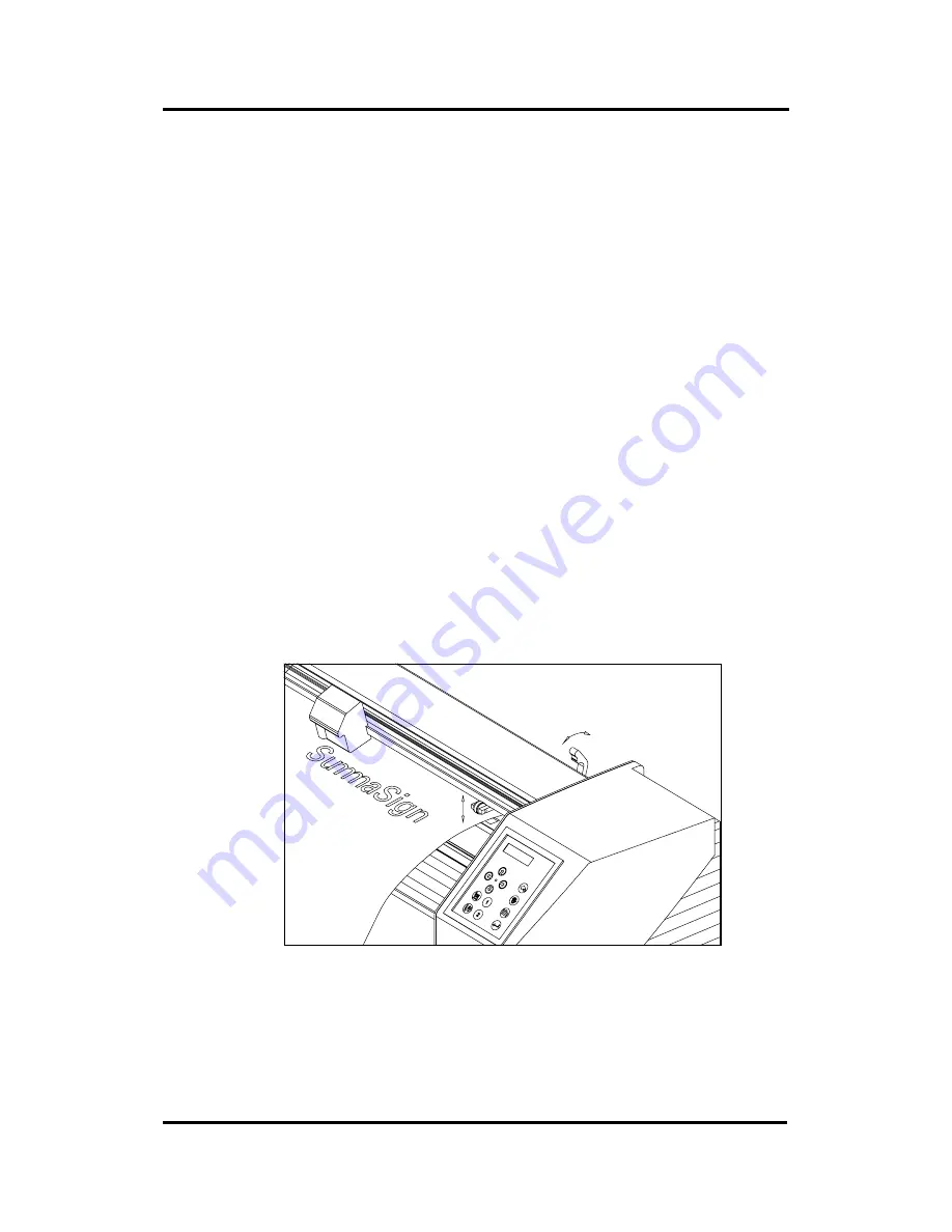
1. Raise the pinch rollers by lowering the pinch roller lever located at the back
of the cutter.
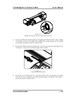
FIGURE 1-8:
MEDIA POSITIONING
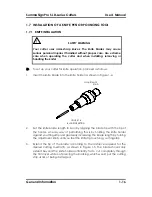
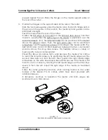
2. When working with roll media, proceed by inserting a media flange at
each end of the roll and then tighten the thumbscrews until the media roll is
firmly gripped between the flanges. Make sure the flanges are firmly


