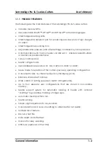

SummaSign Pro SL T-series Cutters
User’s Manual
General Information
1-8
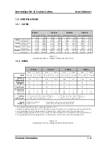
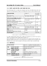
2.8. ENVIRONMENTAL
(cutter without media)
Operating Temperature
15 to 35
°
C
59 to 95
°
F
Storage temperature
-30 to 70
°
C
-22 to 158
°
F
Relative humidity
35 - 85 %, non con-
densing
35 - 85 %, non con-
densing
TABLE 1-7:
SUMMASIGN PRO SL T-SERIES ENVIRONMENTAL SPECIFICATIONS
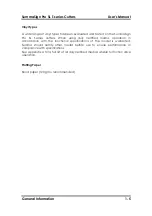
IMPORTANT HINT
The use of dimensionally stable media is an essential prerequisite to
obtaining high cut quality. Additionally, media expansion or
contraction may occur as a result of temperature variations.
To improve the dimensional stability of media, allow it to acclimate to
the current environmental conditions for at least 24 hours prior to use.
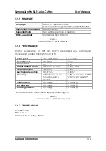
1.2.8
ELECTRICAL
Main Supply: 48-62 Hz, single phase.
Nominal line
Min./Max. line
Fuse
100 V AC
89 - 108 V AC
1.25 A, Slo-Blo
120 V AC
108 - 130 V AC
1.25 A, Slo-Blo
220 V AC
197 - 238 V AC
0.6 A, Slo-Blo
240 V AC
216 - 260 V AC
0.6 A, Slo-Blo
TABLE 1-8:
SUMMASIGN PRO SL T-SERIES ELECTRICAL SPECIFICATIONS


