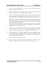
SummaSign Pro SL T-series Cutters
User’s Manual
General Information
1-11
1.
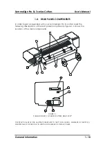
USB Port: -
This interface is based on the standards specified in Universal
Serial Bus Specifications Revision 1.1. It provides high-speed serial bi-
directional communication between the host computer and the cutter.
2.
RS-232-C Port: -
This DB-9P connector provides bidirectional
communication between the host computer and the cutter.
3.
Parallel Port: -
This 36-pin Centronics connector provides unidirectional
communication between the host computer and the cutter. The cutter
can receive but not transmit data via this port.
Note: Only one of the above three interfaces can be active at any one
time.
The first port that receives data will be the active interface until the cutter
is reset.
4.
Power
ON/OFF switch
: - This rocker switch turns the cutter on and off. To
switch the power ON, press the “I” side of the rocker switch. To switch the
power OFF, press the “O” side of the rocker switch.
5.
Power Entry Module: -
The fuse box, the voltage select board, and the AC
power cord receptacle are located in the power entry module.
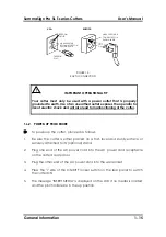
The power-up procedure is explained in detail in Section 1.6.
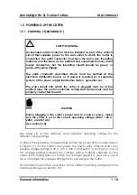
For information about the conversion of the cutter's operating voltage,
see Section 3.2.
6.
Roll
Media Guides:
- The two guides keep the roll in place laterally as the
media is pulled free. The guides also keep the media flanges in place
laterally when the flanges are being used to hold the roll.
7.
Media Flanges
: - The media flanges ensure proper routing of the media
roll.
8.
Media Support Rollers:
- Rotating rollers that support the media roll.

