SummaSign Pro SL D-series Cutters
User’s Manual
Operation
2-27
2.6.4
OPTICAL SENSOR
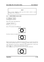
OPTICAL SENSOR is used to check whether or not the OPOS sensor is functioning
properly. If the sensor is positioned over black media, the sensor output should
be High (above 1500). If the sensor is positioned over white media, the sensor
output should be low (below 400).
2.6.5
SENSOR SETUP
SENSOR SETUP is used to check whether or not the front and rear media sensors
are functioning properly, and whether the switching levels of these sensors are
set correctly.
2.6.6
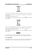
CALIBRATE X/Y
CALIBRATE X/Y cuts two perpendicular lines in the media. The user then
measures these lines manually and the results entered through the control
panel.
For example, if the LCD indicates that one of the lines should measure 100 mm,
but manual measurement indicates 105 mm, then 105 mm can be entered for
that particular line by which the system will be calibrated.
2.6.7
RS232 TEST
The RS232 TEST verifies the cutter’s RS-232-C serial communications (transmit
data, receive data, and hardware handshaking) circuits. This test does not
require that a pen, knife or media be loaded.
Î
To run the RS-232-C test, proceed as follows:
1.
Unplug the RS-232-C data cable from the rear panel of the cutter.
2.
Use a loopback test cable to connect pin 2 of the cutter’s data
connector to pin 3; connect pin 7 to pin 8.
3.
With RS232 TEST displayed, press the ENTER key. The cutter will start
transmitting and receiving data at all available baud rates and parity
settings. The length of the transmissions will vary because of the different
baud rates used. The unit then checks the hardware handshake lines.
4.
Upon completion of the test, remove the loopback test cable from the
cutter rear panel RS-232-C connector.
5.
Reattach the RS-232-C data cable to the connector.

