SummaSign Pro SL T-series Cutters
User’s Manual
Interface
4-2
2. The default settings of the cutter are as follow:
•
Baudrate
: 9600 (see 2.3.8.)
•
Data Bits
: 8
•
Parity
: None (see 2.3.9.)
•
Stop Bits
: 2
•
Flow Control : Hardware
4.2.2
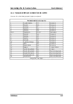
SERIAL INTERFACE CONNECTOR ON THE CUTTER
RS-232C Serial Interface Connector
Pin n°
Signal
Description
1
NC
Not Connected
2
RXD
Receive Data
3
TXD
Transmit Data
4
DTR
Data Terminal Ready
5
GND
Signal ground
6
NC
Not connected
7
RTS
Request To Send
8
CTS
Clear To Send
9
NC
Not Connected
4.2.3
AVAILABLE SERIAL SIGNALS
If you are making your own cable, only a few of the cutter’s pins will actually
need to be connected to the host computer. To ensure optimal results, the
cable length should not exceed 4.8 m (16 feet). It should be taken into account
that your computer or cutting software may also require additional loopback
connections at the host computer's end of the data cable.
•
Connect the computer’s Transmit Data (TXD) pin to pin #2 on the cutter.
•
Connect the computer’s Receive Data (RXD) pin to pin #3 on the cutter.
•
For hardware handshaking, connect the computer’s Clear To Send (CTS)
pin to pin #4 or pin #7 on the cutter. Connect the computer’s Request To
Send (RTS) pin to pin #8 on the cutter.
•
Connect the computer’s ground (GND) pin to pin #5 on the cutter.

