background image

SummaSign Pro T-series Cutters

User’ s Manual

General Information 

1-12

1.5. FRONT PANEL CONTROLS

In order to get acquainted with your SummaSign Pro cutter, read the following
description of the front panel controls and components.
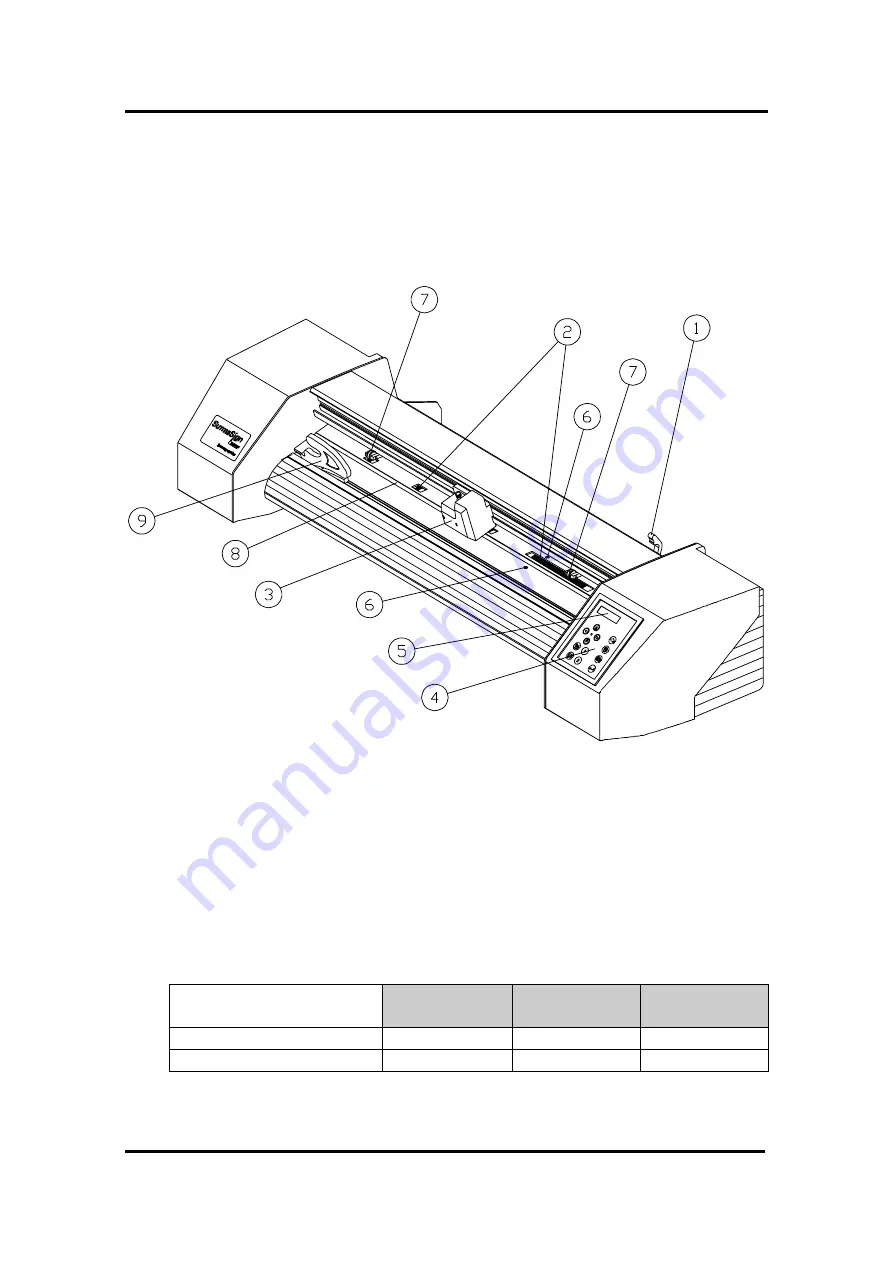
Figure 1-2 shows the location of the main components.

FIGURE 1-2 :

SUMMASIGN PRO T-SERIES CUTTERS, FRONT VIEW

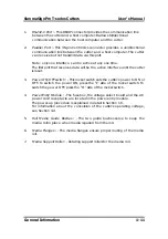
1. 

Pinch roller lever arm


:

 - This lever is used to raise and lower the pinch

rollers (Media loading is discussed in Section 1.8).

2.

Media Drive Sleeves

 : -  The media drive sleeves move the media only

when the pinch rollers are in the ‘down’ position.
The following table lists the number of  media drive  sleeves installed on
each model of the Pro T-series cutters.

Number of media drive
sleeves

T750 Pro

T1010 Pro

T1400 Pro

Short sleeve

5

6

8

Long sleeve

1

1

1

3.

Tool Carriage : -

  The tool carriage is the mount for the tangential cutting

head.

Summary of Contents for T1010 Pro

Page 1: ......

Page 2: ...n html Users outside Europe Africa and the Middle East should check the address on the back of the Warranty Registration Card Failure to return the duly completed Warranty Registration Card or Online...

Page 3: ...th the instruction manual may cause harmful interference to radio communications Operation of these cutters in a residential area is likely to cause harmful interference in which case the user will be...

Page 4: ...All rights reserved All queries comments or suggestions concerning this and other Summa manuals should be directed to Americas and Asia Pacific Summa Inc 10001 Lake City Way NE SEATTLE WA 98125 USA Te...

Page 5: ...ic Products Inc Grafitack is a trademark of Grafityp HP GL is a trademark of Hewlett Packard Company IBM PC IBM PC XT and IBM AT are trademarks of International Business Machines Corp Kapco is a trade...

Page 6: ...trical 1 8 1 3 Cutter options accessories and consumables 1 9 1 4 Rear panel components 1 10 1 5 Front panel controls 1 12 1 6 Powering up the cutter 1 14 1 6 1 Earthing 1 14 1 6 2 Power up procedure...

Page 7: ...eration 2 8 2 3 The USER CONFIG menu 2 9 2 3 1 Knife pressure 2 11 2 3 2 Pen pressure 2 11 2 3 3 Pouncing pressure 2 11 2 3 4 Knife offset 2 11 2 3 5 Pouncing gap 2 12 2 3 6 Velocity 2 12 2 3 7 Overcu...

Page 8: ...e 2 27 2 6 2 ROM revision 2 27 2 6 3 Service plot 2 27 2 6 4 Sensor setup 2 28 2 6 5 Calibration 2 28 2 6 6 Tracking test 2 28 2 6 7 Friction plot 2 28 2 6 8 RS232 test 2 28 2 6 9 RAM test 2 29 2 6 10...

Page 9: ...the cross marks 5 9 5 8 Cutting the contour 5 11 APPENDIX A Media certification A 1 LIST OF ILLUSTRATIONS 1 1 SummaSign Pro T series cutter rear view 1 10 1 2 SummaSign Pro T series cutter front view...

Page 10: ...3 2 Location of the sensors 3 2 3 3 Power entry module 3 4 LIST OF TABLES 1 1 SummaSign Pro T series cutter specifications 1 4 1 2 SummaSign Pro T series media specifications 1 4 1 2 SummaSign Pro T...

Page 11: ...the following SummaSign Pro T series cutter models The SummaSign T750 Pro which can handle media widths from 60 mm up to 762 mm 2 4 to 30 The SummaSign T1010 Pro which can handle media widths from 110...

Page 12: ...de for selection of the cutter s power up operating configuration Convenient operator control via a 2 line 16 character liquid crystal display Extensive internal test routines Wide variety of cutting...

Page 13: ...ete description of the SummaSign Pro T series main components Step by step instructions for knife and ballpoint pen installation and media loading Instructions for online and local mode operations Ins...

Page 14: ...ithout stand 31 kg 68 lbs 38 kg 84lbs 43 kg 93 lbs with stand 46 kg 101 lbs 54 kg 119 lbs 61 kg 134 lbs TABLE 1 1 SUMMASIGN PRO T SERIES CUTTER SPECIFICATIONS 1 2 2 MEDIA T750 Pro T1010 Pro T1400 Pro...

Page 15: ...dia size and other parameters Media lengths greater than 4 m 13 feet can be handled but compliance with specifications is not guaranteed will be dependent on media type media size and other parameters...

Page 16: ...g knife holder standard reflective fluorescent vinyl types 1 off 1 off Pen Colour Quantity Ballpoint pen requires a ballpoint pen holder black 1 off 1 off Pouncing Tool Paper optional TABLE 1 3 SUMMAS...

Page 17: ...mm 0 010 Axial speed 50 to 1000 mm s 2 to 40 ips Default speed 800 mm s 32 ips Acceleration 3 G 3 G Addressable resolution 0 025 mm 0 1 mm 0 001 0 005 Default resolution 0 025 mm 0 001 Mechanical reso...

Page 18: ...ssential pre requisite to obtaining high cut quality Additionally media expansion or contraction may occur as a result of temperature variations To improve the dimensional stability of media let it st...

Page 19: ...erial Interface Kit consisting of 9 pin to 9 pin cable 9 pin to 8 pin DIN conv 423 155 TANGENTIAL knife holder 391 663 Standard TANGENTIAL knife 1 off 390 549 Double tip knife 390 551 Standard nose pi...

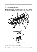
Page 20: ...your SummaSign Pro cutter read the following description of the rear panel components Figure 1 1 shows the location of the main components FIGURE 1 1 SUMMASIGN PRO T SERIES CUTTERS REAR VIEW FOR PRAC...

Page 21: ...until the cutter is reset 3 Power ON OFF switch This rocker switch sets the cutter s power to ON or OFF To switch the power ON press the I side of the rocker switch To switch the power OFF press the O...

Page 22: ...VIEW 1 Pinch roller lever arm This lever is used to raise and lower the pinch rollers Media loading is discussed in Section 1 8 2 Media Drive Sleeves The media drive sleeves move the media only when t...

Page 23: ...all the way to the front edge of the platen 7 Pinch rollers The pinch rollers one at each side hold the media clamped between the rubber rollers and the media drive sleeves The T1010 and T1300 units...

Page 24: ...the earthed type The earth conductors serving said wall sockets must be properly connected to earth CAUTION Before plugging in the cutter s power cord to a power source make sure the cutter is set to...

Page 25: ...c shock and will also lead to malfunctioning of the cutter 1 6 2 POWER UP PROCEDURE To power up the cutter proceed as follows 1 Be sure the cutter is either placed on a flat level and sturdy surface o...

Page 26: ...g the knife To set up your cutter for TANGENTIAL knife operation proceed as follows 1 As shown in Figure 1 4 insert the standard knife blade p n 390 549 into the knife holder Make sure the knife blade...

Page 27: ...E 1 5 NOSE PIECE INSTALLATION 3 Gently insert the knife into the tool shaft as shown in Figure 1 5 Hold the nose piece in place with one hand with the other hand turn the knife holder anticlockwise un...

Page 28: ...ws Load media and power on the cutter Press the key MENU key until the message USER CONFIG 1 is displayed on the LCD USER CONFIG 1 Press the jogging key until the message KNIFE PRESS is displayed KNIF...

Page 29: ...a to be cut adjusting the pressure and depth of the knife will require some practice In general terms you should increase the pressure and depth of the knife when cutting thicker types of vinyl For th...

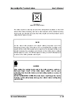
Page 30: ...LING A KNIFE FOR CUTTING MASKING STENCIL OR HEAVY MATERIALS 1 As shown in Figure 1 9 insert the knife blade into the knife holder Make sure the knife blade is firmly fixed into the holder The blade is...

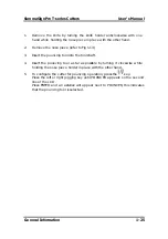
Page 31: ...t Then turn the knife holder clockwise until it gets grip in the tool shaft 4 For knife pressure and depth setting refer to section 1 7 1 point 4 and 5 NOTE When cutting masking stencil or heavy mater...

Page 32: ...nose piece in place with the other hand 2 Insert the drag blade into the drag knife holder as shown in Figure 1 11 FIGURE 1 11 DRAG KNIFE ASSEMBLY 3 Remove the nose piece refer to Fig 1 12 4 Insert th...

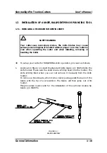
Page 33: ...MENU 6 To set the pressure of the drag knife refer to paragraph 1 7 1 point 5 7 To set the knife offset perform the knife offset test described in paragraph 2 3 3 1 7 4 INSTALLING A BALLPOINT PEN The...

Page 34: ...llpoint pen operation press the key Press the left or right jogging key until BALLPOINT appears on the second line of the LCD Press ENTER and an asterisk will appear next to BALLPOINT this indicates t...

Page 35: ...14 3 Insert the pouncing tool into the tool shaft 4 Insert the pouncing tool as far as possible by turning it clockwise while holding the nose piece holder in place with the other hand 5 To configure...

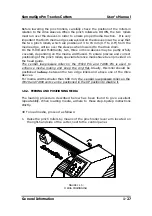
Page 36: ...to the control panel The rollers must be lifted to facilitate vinyl loading when the media is fed from the rear of the cutter to the front When in the up position the pinch rollers can be moved manua...

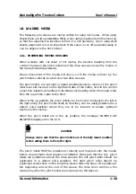
Page 37: ...rrect positioning of the pinch rollers special reference marks have been provided on the head guide The central low pressure roller on the T1010 Pro and T1400 Pro is used to enhance media routing and...

Page 38: ...ned in a detented position over the left most sleeve and the right pinch roller is positioned somewhere over the long drive sleeve to suit the media width The pinch roller can be lowered anywhere betw...

Page 39: ...be positioned over the drive sleeves about 3 to 15 mm 0 1 to 0 6 away from the media s outer edges For wide media on the T1010 Pro and T1400 Pro units slide the central low pressure roller into positi...

Page 40: ...cally moves from the right to the left to sense the usable media width NOTE It is not necessary to unroll the media manually from the roll The cutter will unroll the media automatically during the loa...

Page 41: ...nimal loading procedure consisting of a media width measurement a 45 test media is unwound over a length equal to the width measured between the pinch rollers When the next display appears the cutter...

Page 42: ...IN X 0 Y YYYY Using the jogging keys you can position the knife i e the origin at any location Press the key to confirm the selected point of origin MEDIA WINDOW By pressing the jogging keys you can e...

Page 43: ...E 1 The cutter is now ready to receive a file 800mm s 120 g K ONLINE 1 The cutter has been selected by the computer When the built in media sensors detect the end of the roll the message END OF MEDIA...

Page 44: ...PANEL Figure 2 1 shows the control panel of the SummaSign Pro T series cutters The main functions of the liquid crystal display LCD and the control panel keys are explained in the following paragraph...

Page 45: ...play 2 1 2 THE RESET LOAD KEY The key RESET LOAD is used to move the origin to initiate a load sequence to reset the cutter to abort the cut in progress or to recut the last file When the key RESET LO...

Page 46: ...rations can be performed Press the or jogging key to move the tool carriage to the left or right Press the or jogging key to make the media move forward towards you or backward away from you Moving th...

Page 47: ...ons press the jogging key To exit from the menus and resume the previous on line operation press the key ON LINE Under normal conditions the cutter is on line it may then be selected by the host compu...

Page 48: ...use of the 1 and 2 keys varies according to the operation in progress their use is displayed on the LCD as appropriate 2 1 7 THE JOGGING KEYS The use of the jogging keys varies according to the operat...

Page 49: ...ife a ballpoint pen a pouncing tool To temporarily change the tool press the key then press the or jogging key until the desired tool appears on the second line o the LCD Press the key to confirm the...

Page 50: ...to receive data 1 user number In all other cases the cutter is off line When on line the cutter can be addressed by the host computer which means that the cutter will execute cutting or plotting inst...

Page 51: ...end the current cutting plotting operation until the cutter is put on line again 2 2 2 LOCAL OPERATION Local operation is only possible while the cutter is off line Local operation means that the cutt...

Page 52: ...er 2 Press the key until USER CONFIG 1 4 is displayed 3 Press the or jogging key until the desired configuration number is displayed next to USER CONFIG NOTE Before altering any of the items in the US...

Page 53: ...SummaSign Pro T series Cutters User s Manual Operation 2 10 IN DM PL ONLY IN HP GL AND HP GL 2 ONLY FIGURE 2 3 FLOWCHART SHOWING FACTORY PRESET MENU SETTINGS...

Page 54: ...PRESSURE The POUNCING PRESSURE submenu is used to set or modify the pressure of the pouncing tool The default pouncing pressure value is 120 grams The pressure can be set between 0 and 600 grams in 5...

Page 55: ...mm s 32 ips The velocity can be set between 50 mm s 2 ips and 1000 mm s 40 ips 2 3 7 OVERCUT The OVERCUT submenu enables you to generate an overcut in order to facilitate weeding the cut The default o...

Page 56: ...the active setting is marked with an 2 4 3 EMULATE The EMULATE submenu is used to select the active cutting plotting language for the cutter The SummaSign Pro cutters support DM PL HP GL and HP GL 2 O...

Page 57: ...c menu units for DM PL In HP GL HP GL 2 the menu units are always in metric For models sold in the US English units are the default setting For models sold in Europe metric units are the default setti...

Page 58: ...ng Remarks BIT 8 0 8 data bits no parity bit 8 low 0 BIT 8 1 8 data bits no parity bit 8 high 1 EVEN 7 data bits 1 parity bit parity bit even ODD 7 data bits 1 parity bit parity bit odd On the LCD the...

Page 59: ...the LCD This menu will only be displayed if PLOT LANGUAGE is set to HP GL The HP GL ERRORS submenu can be set to REPORTED or IGNORED On the LCD the active setting is marked with an The feature is acti...

Page 60: ...GL pen knife select commands the P and SP commands respectively are ignored or accepted When the TOOL COMMAND option is set to ACCEPT the P or SP commands will change the selected tool in the cutter a...

Page 61: ...Pressing the 1 key will activate the configuration menu which allows you to set the cutting pressure and the cut length 1 CUT LENGTH This parameter determines the length that is cut with full pressure...

Page 62: ...pen 4 Press the key until INTERNAL TEST is displayed and press the jogging key 5 Press the or jogging key until the desired internal test is displayed 6 To perform the test press the key To exit from...

Page 63: ...de This routine should only be run when required When noticing cut quality problems with a new knife perform a knife calibration test as described in the following paragraphs During the knife calibrat...

Page 64: ...utine Vertical misalignment The knife tip deviates from its theoretical lateral centre This error can be corrected by means of the ADJUST LAT test routine LONGITUDINAL deviation LATERAL deviation Theo...

Page 65: ...n illustrated above If you obtained this kind of pattern increase the value displayed on the LCD by pressing the jogging key to correct closing of the circles cut To repeat the test press the key Pres...

Page 66: ...tal line at the top 4 runs from the centre to the horizontal line at the bottom Carefully check the alignment of the different cuts the two vertical lines should meet seamlessly precisely in the middl...

Page 67: ...orm the vertical test shown above All the squares should be identical Press the key to go to the next step of the procedure 2 5 1 3 ADJUST LONG test routine ADJUST LONG 0 1 Press to execute the LONG t...

Page 68: ...test has been added to fine tune the LONG adjustment Press the 1 key to perform the horizontal test all the squares should be identical 2 5 2 CUT BORDER The CUT BORDER submenu is used to cut the bord...

Page 69: ...2 5 5 DIN CUT The DIN CUT also performs an electrical and mechanical test of the cutter in order to check the cut quality but also provides the user with feedback on knife setting knife pressure knif...

Page 70: ...can be displayed in English French German Dutch Spanish or Italian 2 6 2 ROM REVISION Selecting the ROM REVISION option by pressing the key will furnish the details on the cutter s ROM revision This i...

Page 71: ...d to fit the currently installed paper size This test should only be performed by qualified service personnel 2 6 8 RS232 TEST The RS232 TEST routine verifies the cutter s RS 232 C serial communicatio...

Page 72: ...1 COIL SETUP This test is used to calibrate knife and pen pressure and to set the knife and pen landing After adjustment the value is saved in the system s non volatile RAM To execute this test a tens...

Page 73: ...ulated residue from the media This situation may affect traction as the media will tend to slip between the pinch rollers and the drive sleeves To clean the drive sleeves proceed as follows 1 First di...

Page 74: ...E 3 1 CLEANING OF THE DRIVE SLEEVES 3 1 2 CLEANING THE SENSORS After a certain time the sensor may become dirty with accumulated residue from the media This situation may cause malfunctioning of the c...

Page 75: ...esidue from the vinyl and will result in poor cut quality To clean the nose piece proceed as follows 1 Gently take out the knife or ball point pen by turning the knife holder anticlockwise 2 Observe t...

Page 76: ...plied to your site you must change the voltage BEFORE powering on the cutter When changing the voltage setting you will also have to change the fuses as appropriate to the voltage To change the fuse s...

Page 77: ...ters 2 If the documentation of the cutting plotting software does not contain specific cabling instructions use the Summa cable specifications recommended for your computer 4 2 INTERFACE NOTES 4 2 1 S...

Page 78: ...ceed as follows 1 Select Main group in the Program Manager Select Control Panel then Ports and then the port that is connected to the cutter Press the Settings Button to see the port settings 2 The de...

Page 79: ...CTOR ON CUTTER The use of a shielded parallel cable is required Parrallel interface Connector Pin n Definition Pin n Definition 1 Data Strobe 19 Ground 2 Data 1 20 Ground 3 Data 2 21 Ground 4 Data 3 2...

Page 80: ...our computer or cutting software may also require additional loopback connections at the host computer s end of the data cable Connect the Transmit Data TXD pin of the computer to pin 2 of the cutter...

Page 81: ...ROTATED DESIGN If the printed design is not loaded straight into the unit the contour can be rotated equally to fit the printed graphic 2 SKEWED DESIGN If the X and Y axes of the printed design are no...

Page 82: ...t Any combination of the three above irregularities can be handled too The parameter SPECIAL_LOAD in the user configuration menu determines which alignment method is used This parameter can be changed...

Page 83: ...jogging key until the message SYSTEM SETUP is displayed SYSTEM SETUP Press the jogging key until the message SPECIAL LOAD is displayed SPECIAL LOAD X ALIGN Press the or key to modify the special load...

Page 84: ...17 2 XY Alignment counterbalances the rotated design and skewed design problems For this method the origin one point along the x axis and one point along the y axis must be specified This method rota...

Page 85: ...ks around your design Print out the design with the cross marks Load the printed design in the cutter and set the cross mark parameters in the cutter only when using the XY adjustment method Execute t...

Page 86: ...h the design and the contour 5 4 PLACING THE CROSS MARKS Place two cross marks indicating the X axis Make sure that the origin cross mark is situated completely at the left side and below all the cont...

Page 87: ...nd the origin must be known only when using the XY Adjustment method Do not measure these distances on the print out but measure them in the software Place the markers as far as possible from each oth...

Page 88: ...the cutter as described in the User s Manual Make sure that the cross mark indicating the origin is situated at the front right If you have selected the XY adjustment method see above then open Summa...

Page 89: ...ressure velocity See User s Manual Press the key until the message SPECIAL LOAD is displayed on the LCD SPECIAL LOAD Press the key DIGITIZE ORIGIN X 0 Y 0 Position the knife tip exactly above the orig...

Page 90: ...ition the knife tip exactly above the mark indicating the X axis Press the key If the X axis alignment method has been choosen the special load procedure will stop here For the two other methods posit...

Page 91: ...mark is situated in the lower left corner of the cutting area In most sign making software the orientation is landscape If not you will have to rotate everything Select the contours and cut them out M...

Page 92: ...SummaSign Pro T series Cutters User s Manual Contour Cutting 5 12 Origin Incorrect Correct Origin...

Page 93: ...certified media is included below Before using other media please contact your local Summa representative for advice Manufacturer Type 3 M Scotchcal Series 100 Scotchcal Series 3480 Scotchcal Transluc...

Page 94: ...mmasign Pro T series Cutters User s Manual Appendix A 2 MULTIFIX Series 1000 Series 5000 Series 7000 MULTISTIQ Series 4500 Series 4600 Series 4700 PMF Series 500 600 700 TESA Tesacal 4196 X FILM Econo...

Page 95: ...RESSES Americas and Asia Pacific Summa Inc 10001 Lake City Way NE SEATTLE WA 98125 USA Tel 01 206 527 1050 Fax 01 206 527 1046 E mail support summausa com Europe Summa NV Rochesterlaan 6 8470 GISTEL B...

Reviews: