8
9
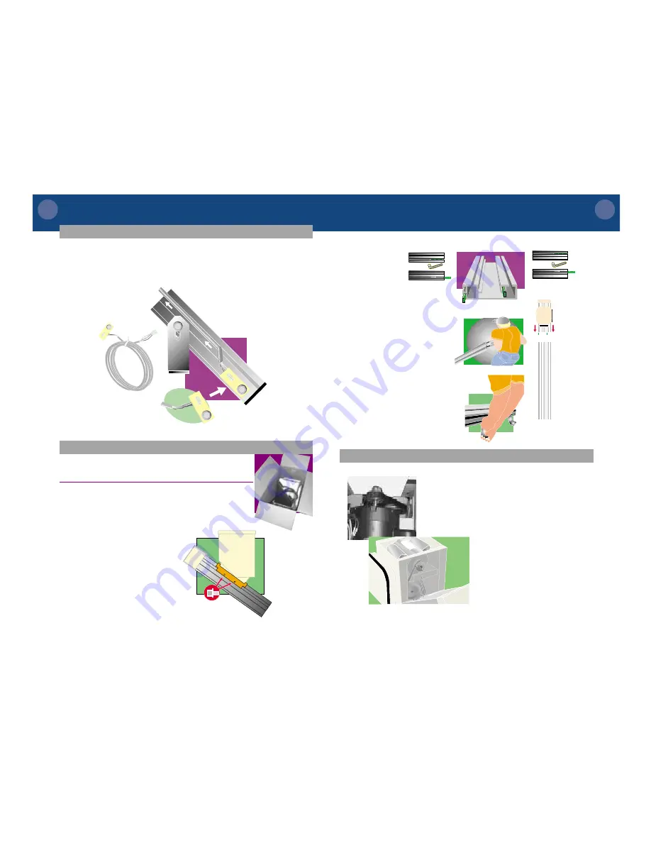
R O U T I N G
T H E
L O W E R
C A L L
C O N T R O L
W I R E
1
Attach call control bracket to the
nut between the bottom bracket
and the bottom of the track.
2
Route the wire through
the top track channel
on the wall-side of the
track.
3
At the top of the middle section
of track, tuck the wire underneath
the track out of the way.
4
You will finish routing the call
control wire after the top track
section is in place.
1
Open unit box by cutting down
the sides of the box. Fold the
sides of the box down and slide
the unit and top track to the edge
of the steps.
2
Remove cardboard packing from
back of footrest.
3
Remove the shipping brace from
the upper section of track and set
aside.
CAUTION:
Assistance may be needed for this part of the
installation due to unit’s and upper track section’s weight.
I
N
S
T
A
L
L
I
N
G
T
H
E
U
N
I
T
NOTE:
Do not unpack
cables from magazine
holder yet.
4
Loosen the
splice bars
from their
shipping
position
and slide
them out to half way.
Tighten the splice bars.
5
Slide the upper track
section onto the lower
track section. Tighten the
splice bar set screws to
lock tracks together.
The
tracks will not slide
together if the set screws
protrude beyond the splice
bar.
6
Attach track brackets to
the side of the top track
section. Hand tighten.
ALLEN WRENCH
ALLEN WRENCH
track section showing position of splice bars
wall-side splice bar
stair-side splice bar
CAUTION:
Do not put
your
fingers
between
the track
sections at
any time as
injury
could
occur.
S L A C K
C A B L E
R E S E T
P R O C E D U R E
1
During shipping, the slack cable
device may engage and need to
be reset.
The slack cable safety prevents
the lift from running when there
is not enough tension on the
cable.
2
With the unit and upper track
section installed and power cable
unplugged, you will use your hand
to turn the motor belt that turns
the cable drum.
The illustrations show overhead
and cut-away views of the unit.


