


12
13
I
N
S
T
A
L
L
I
N
G
T
H
E
S
E
A
T
3
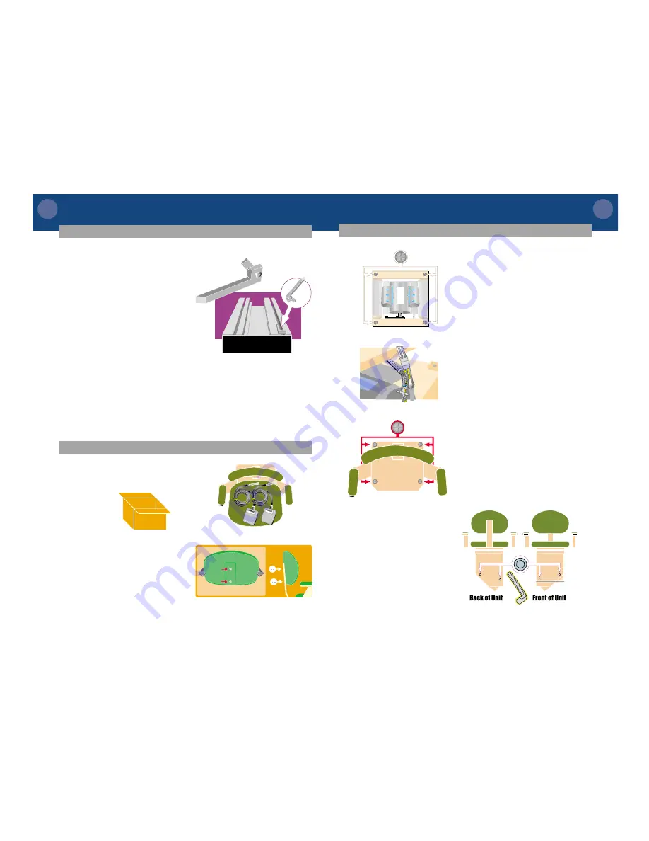
Remove the four screws from the
top of the unit. Set the screws/
washers aside.
CAUTION: Be
careful not to drop screws/
washers into unit while removing.
4
Set seat on top of unit chassis.
Tip seat sideways and locate seat
control wire. Plug into the unit
seat control wire. Plugs can only
go together one way.
5
Lower the seat to the unit
chassis. Screw in place with four
screws and lock washers previ-
ously set aside. Pull up on swivel
arm to rotate the seat to gain
access to all 4 holes.
6
If the seat is not level, then you
will need to adjust the seat
leveling.
7
There are 4 allen screws that hold
the seat level. There are two on
the footrest side of the chassis,
and two on the back side. Loosen
all four a couple of turns (they
cannot be taken out).
8
Firmly level the seat by pushing
up on one arm and down on the
other arm, until the seat is level.
9
Re-tighten the 4 allen screws.
NOTE:
The unit is designed so it
will not run unless the seat is
facing forward and the swivel lock
is in place.
1
The upper and lower limit cams
are safety devices that automati-
cally stop the unit at each
landing. They have been placed
on the track on both sides of the
unit to hold the unit in place
during shipping.
2
Locate the lower limit cam (on
the track under the unit) and
move to the bottom of the track -
butting it against the bottom
track cover and tighten into
place.
Lower limit cam
NOTE:
Before the upper limit cam can be moved to its proper position, the
seat will have to be attached to the unit chassis.
1
Open the seat box and remove the
seat and two call controls from
the box. Set the call controls
aside.
I
N
S
T
A
L
L
I
N
G
T
H
E
S
E
A
T
2
Remove the two screws from the
back of the backrest. Use them to
attach the backrest to the
preferred height position on the
seat back bar.
I N S T A L L I N G
T H E
L O W E R
L I M I T
C A M


