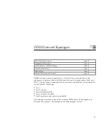
FDDI Network Architecture
55
6
FDDI Network Architecture
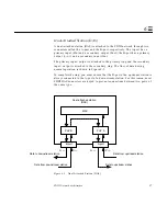
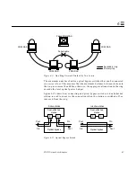
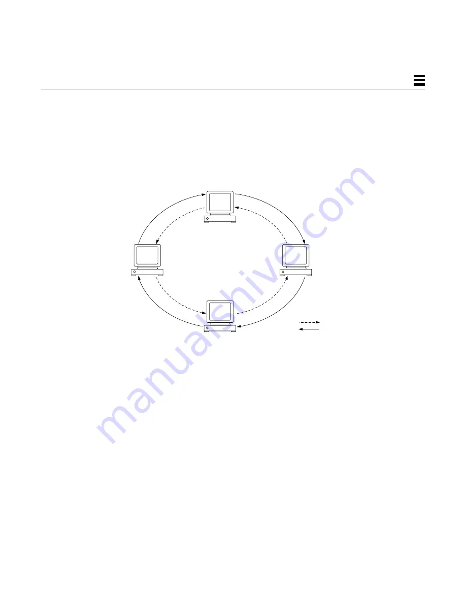
A typical FDDI network is based on a dual, counter-rotating ring, as illustrated
in Figure 6-3. Each FDDI station is connected in sequence to two rings
simultaneously—a primary ring and a secondary ring. Data flows in one
direction on the primary ring, and in the other direction on the secondary ring.
Figure 6-3
Basic FDDI Network Architecture
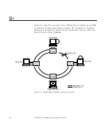
The secondary ring serves as a redundant path. It is used during station
initialization, and may be used as a backup to the primary ring in the event of
a station or cable failure. When a failure occurs, the dual-ring is “wrapped”
around to isolate the fault and to create a single, one-way ring. The
components of a typical FDDI network and the failure recovery mechanism are
described in more detail in the following sections.
FDDI station
FDDI station
FDDI station
FDDI station
Primary ring
Secondary ring
Summary of Contents for 1.0
Page 13: ...Contents xiii Glossary 141 Index 147 ...
Page 14: ...xiv SunFDDI P 1 0 Adapter User s Guide May 1997 ...
Page 18: ...xviii SunFDDI P 1 0 Adapter User s Guide May 1997 ...
Page 25: ...Part1 InstallingandConfiguring SunFDDI P ...
Page 26: ......
Page 36: ...10 SunFDDI P 1 0 Adapter User s Guide May 1997 2 ...
Page 58: ...32 SunFDDI P 1 0 Adapter User s Guide May 1997 4 ...
Page 73: ...Part2 PlanningandImplementing SunFDDINetworks ...
Page 74: ......
Page 94: ...68 SunFDDI P 1 0 Adapter User s Guide May 1997 6 ...
Page 110: ...84 SunFDDI P 1 0 Adapter User s Guide May 1997 7 ...
Page 128: ...102 SunFDDI P 1 0 Adapter User s Guide May 1997 8 ...
Page 144: ...118 SunFDDI P 1 0 Adapter User s Guide May 1997 9 ...
Page 150: ...124 SunFDDI P 1 0 Adapter User s Guide May 1997 10 ...
Page 166: ...140 SunFDDI P 1 0 Adapter User s Guide May 1997 A ...
Page 172: ...146 SunFDDI P 1 0 Adapter User s Guide May 1997 ...
Page 182: ......


