background image

Summary of Contents for 3400

Page 1: ... sun microsystems Sun 3400 CPU Board Installation Manual Part No Part Number 800 2399 11 Revision A of 15 May 1989 ...

Page 2: ...c SUD microsystems Sun 3400 CPU Board Installation Manual ...

Page 3: ...s Le present appareil numerique n emet pas de bruits radioelectriques depassant les limites applicables aux appareils numeriques de la classe A prescrites dans le Reglement sur le brouillage radioelectrique edicte par le ministere des Communications du Canada WARNING There is a Lithium Battery Matsushita Electric Type No BR2325 located on the Sun CPU Board This battery is NOT a customer replaceabl...

Page 4: ...ents 2 3 Removing the Old CPU Board Cautions Concerning the Springfingers Removing a Board 10 Preparing a Board for Return to Sun 10 Obtaining a Replacement Board from Sun 10 2 4 Installing a New 3400 CPU Board 10 Inspecting Boards 10 Installing Chips on a Board 10 Configuring a New CPU Board 11 Installing the New CPU Board 11 Chapter 3 Cabling 3 1 Connecting the Keyboard and the Mouse 3 2 Connect...

Page 5: ...out the Diagnostic LEDs 25 Diagnostic Interpretation of LED Patterns 25 Faults Detected During Self test 26 Console Display 27 Normal Display Blank Display 27 27 4 3 Setting EEPROM Values 28 High Resolution Monitor 28 Appendix A 3400 CPU Board Connector Pinouts and Serial Port Signals 33 Serial Port Signals 35 Appendix B Customer Service Repairs 41 B 1 Removing the CPU Board from the System 41 Wor...

Page 6: ...Contents Continued B 3 Installing the ID PROM and Other Chips 43 Appendix C Power Consumption Tables 47 _ v ...

Page 7: ... ...

Page 8: ... Table A 2 Pinout of Serial Ports A and B Connectors 34 Table A 3 Pinout ofEthernet Connector 34 Table A 4 Pinout of Monochrome Video Connector 35 Table A 5 Description of Serial Port Signals 36 Table C 1 Sun 3400 CPU Board Power Consumption 47 Table C 2 Sun 3400 CPU Board Power Consumption 48 vii ...

Page 9: ......

Page 10: ...s Figure 3 1 Sun 3400 CPU Board Backplate Edge Connectors 15 Figure 3 2 Null Modem Cable Pin Arrangement 17 Figure 3 3 Standard Serial Cable Pin Arrangement 18 Figure A 1 A Typical DTE DCE Configuration 35 ix ...

Page 11: ... ...

Page 12: ...escribes how to connect the keyboard cable and an Ethernet cable to the Sun 3400 CPU board and how to connect a mouse cable to the keyboard This chapter also includes information to help you predetermine compatibility before connecting peripheral devices to the Sun 3400 CPU board s serial ports Power Up and Self Test describes the functions of the Sun 3400 CPU board s switches and LEDs indicators ...

Page 13: ...his sheet and return it to us We would like to emphasize that this Sun 3400 CPU Board Installation Procedures manual outlines rather than exhausts any of the topics it contains The documents listed below include related information We urge you to read these documents should you need further information on related topics A number of Sun systems use the Sun 3400 CPU These systems are shipped with a ...

Page 14: ...0 2018 Sun 501 1102 Memory Board Configuration Procedures 800 2123 Installation Notes for the 32 Mbyte Memory Board 813 2055 Sun 3400 CPU Configuration Procedures 813 2056 Sun 3 460 3 480 Cardcage Slot Assignments and Backplane Configuration Procedures 813 2073 Sun 3 470 Cardcage Slot Assignments and Backplane Configuration Procedures 813 1000 Sun Hardware Options Guide 800 1700 Sun Release 4 0 Do...

Page 15: ... ...

Page 16: ... 1 General Description General Description 3 General Description ofthe Sun 3400 CPU Board 3 ...

Page 17: ..._ ...

Page 18: ...2 floating Point Coprocessor running on the same 33MHz clock as the CPU A VMEbus arbitration and diagnostic mode for DVMA interface testing on the board 64 bit multiplexed address data bus memory with support for both 8MB and 32MB ECC memory boards and the Sun 3 floating Point Accelerator Board The main memory address space is 30 bits P4 bus support that allows a variety ofvideo daughter boards to...

Page 19: ... ...

Page 20: ...PU Board 7 Handling Boards and Components 8 2 3 Removing the Old CPU Board 8 Cautions Concerning the Springfingers 8 Removing a Board 10 Preparing a Board for Return to Sun 1O Obtaining a Replacement Board from Sun 10 2 4 Installing a New 3400 CPU Board 10 Inspecting Boards 10 Installing Chips on a Board 10 Configuring a New CPU Board 11 Installing the New CPU Board 11 ...

Page 21: ......

Page 22: ... 64 inch or 2mm Allen hex wrench to secure the CPU board s backplate in the cardcage o A screwdriver with a flat blade 1 8 inch wide for the screws that secure the cables to the CPU board o A pair of needle nose pliers to remove or install jumpers on the CPU board o An antistatic wrist strap attached to an earth ground location whenever you handle the boards This wrist strap is to conduct electros...

Page 23: ...ard are fragile and should be handled with care to avoid damage Before you attempt to remove or install a board in your system you should read and understand the cautions in this chapter If you have never removed or installed a board before it is recommended that you obtain the help of someone who is experienced in the procedures Before attempting to remove or install any board in your system make...

Page 24: ...w a board WITHOUT springfingers or to the left ofit in a pedestal installation always remove the board WITH the springfingers before removing the board WITHOUT the springfingers a Ifa board WITH springfingers is to be installed below a board WITHOUT springfingers or to the left of it in a pedestal installation always install the board WITHOUT springfingers first Then install the board WIT H spring...

Page 25: ...dence of damage attach a grounded antistatic wrist strap to your wrist Carefully remove the board from the shipping container Save the carton and the packing material for later use 3 Inspect the board for any socketed components that may have worked loose during shipment Place the board on a flat antistatic surface and firmly seat any loose components back in their sockets NOTE When reseating chip...

Page 26: ...the resistance to further inward movement will rapidly increase indicating that the board is nearly seated For information on where to install the CPU memory boards and other options refer to the Cardcage Slot Assignments and Backplane Con figuration Procedures manual that came with the system CAUTION The CPU board should slide easily into its cardcage slot until it makes initial contact with the ...

Page 27: ..._ ...

Page 28: ...ting the Monitor 16 3 4 General Information about the Asynchronous Serial Ports 16 Null Modem Cables 17 Standard Serial Cables 18 3 5 Connecting a Printer Modem or Terminal 18 Connecting a Printer to Your Sun 3400 CPU Board 18 Connecting a Modem to your Sun 3400 CPU Board 19 Connecting a Terminal to Your Sun 3400 CPU Board 20 ...

Page 29: ......

Page 30: ... side to the right Sun 3400 CPU Board Backplate Edge Connectors Color Option QnosOsOGOR a o 0 Ethernet Serial Port A Serial Port B Keybrd Mouse o oJ a o o o o Jo 0 1 i 1 One end of the keyboard cable is permanently attached to the system s key board The other end of the keyboard cable terminates in a male 15 pin sub miniature D connector Plug the connector on the end ofthe keyboard cable into the ...

Page 31: ...ion manual shipped with the system For either monochrome or color monitors the frame buffer board is mounted as a daughter board on the CPU board This daughter board s edge connectors are labeled VIDEO S B G and R For instructions on connecting the monitor video cables to either the monochrome or color daughter boards refer to the ins tallation guide that came with your particular frame buffer boa...

Page 32: ...nications Equipment ports This means that most of the pin assignments are different For example the DCE peripheral transmits data out pin 3 and receives data in from the system on Rin 2 Signals carried on the CPU board s SERIAL PORT A connector and SERIAL PORT B connector are described in Appendix A Null modem cables Sun P N 530 1056 are used for serial communication between two devices when both ...

Page 33: ...the serial interface and the required cabling refer to Appendix A ofthis manual and to the SunOS Interface Reference Manual sec tion ZS 4S These procedures are guidelines for the connection of peripherals to the serial ports The connection of peripheral devices may require the more detailed infor mation that is contained in the SunOS Interface Reference Manual and the manual accompanying the perip...

Page 34: ...ur printer and the System and Network Administration for the Sun Workstation manual for more complete printer connection information Before trying to connect your modem to a serial port on your 3400 CPU board s backplate you must first determine if your modem s serial interface is a DTE type or a DCE type Most modems are wired as a DCE type Ifyour modem s serial interface is the common DCE type yo...

Page 35: ...that must be resolved before the tenninal will work properly with your system Refer to the manual that came with your tenninal to ascertain that the signals needed to operate the tenni nal are provided at the correct pins of the serial port Ifthe pinouts are all correct follow the installation procedure detailed in the terminal s manual Refer to the System and Network Administrationfor the Sun Wor...

Page 36: ...h 24 The Reset Switch 24 4 2 Power up and Self tests 24 Memory Tests 24 General Infonnation about the Diagnostic LEDs 25 Diagnostic Interpretation ofLED Patterns 25 Faults Detected During Self test 26 Console Display 27 Nonnal Display 27 Blank Display 27 4 3 Setting EEPROM Values 28 High Resolution Monitor 28 8 ...

Page 37: ... ...

Page 38: ...he system and that you have taken all the precautions and followed the procedures outlined in the installation manual before applying power to the system 4 1 Conventions Used in This Chapter Anything printed in typewriter font in this text is a reproduction of a screen display For example Testing 32 megabytes of memory Completed Boldfaced text within that display means that you must enter that inf...

Page 39: ...OM programming explained more fully in the Sun PROM Manual and you may see a on the screen the PROM monitor prompt The RESET switch is located between the LEDs and the DIAG NORM switch It is a momentary contact switch Pressing the RESET switch causes the 3400 CPU board to perform a cold reboot Do not press this switch unless there is a prob lem that less drastic measures cannot solve DO NOT SWITCH...

Page 40: ...SunOS is in a boot state After the SunOS is running the LEDs flash rapidly in a regular signature pattern The signature pattern for the 3400 CPU board is LED O then 0 and 1 light together then 0 1 and 2 light together then 0 1 2 3 then then 0 1 2 3 4 5 6 and 7 This pattern continually repeats as long as the CPU is processing or waiting to process instructions Table 4 1 on the following page provid...

Page 41: ...Test s 0 0 0 0 0 0 Central Cache Data RAM Test s 0 0 0 0 0 Central Cache Hit Miss Test s 0 0 0 0 0 Block Copy Test s 0 0 0 0 Memory Write Write Read Test Central Cache on 0 0 0 0 0 0 0 IOC Tag RAM Test s 0 0 0 0 0 IOC Data RAM Test s 0 0 0 0 0 0 VME Loopback Test 0 0 0 0 0 VME Loopback and DVMA 0 0 0 0 0 0 IOC Read Write Flush Test s 0 0 0 0 0 P4 Overlay Frame Buffer Test s If during a self test L...

Page 42: ...ry portion of the power up self tests has failed and you should contact your Sun Customer Support Center If the LEDs indicate that self tests were successful and that SunOS is booting but the console screen remains blank for more than 30 seconds after power up make sure that o The monitor CRT is cabled correctly o The AC power is switched ON o The DIAG NORM switch is set to the NORM position If th...

Page 43: ...tion OxOlF should be Ox20 After you finish your query in this example your monitor should show the following display q lF RETURN EEPROM 01F 20 4 If you wish to change a value in the EEPROM check the following table Type the appropriate hexadecimal value then type any non hexadecimal character such as a period and then press the RETURN key Screen size is determined dynamically in the Boot PROM Disp...

Page 44: ... may wish to set your high resolution monitor for its full screen display The values are Location Value Configuration Ox050 Ox78 120 columns Ox051 Ox30 48 rows Check your software manual to ensure that there will be no incompatibilities between your software and the display size Revision A of 15 May 1989 ...

Page 45: ... _ ...

Page 46: ... A 3400 CPU Board Connector Pinouts and Serial Port Signals 3400 CPU Board Connector Pinouts and Serial Port Signals 33 Serial Port Signals 35 ...

Page 47: ...l ...

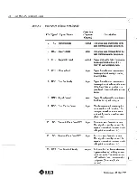
Page 48: ... s a Ethernet Connector a Monochrome Video Connector It also contains a signal description of the serial ports NOTE Only electrically connected pins are listed open circuitpins are not docu mented Table A 1 Pinout ofKeyboard Mouse Connector Keyboard Mouse Pinout Pin Signal Pin Signal 1 RXDA Keyboard 5 RXDB mouse 2 GND 6 GND 3 TXDA Keyboard 14 vcc 4 GND 7 vcc 33 Revision A of 15 May 1989 ...

Page 49: ... DB 4 ATS 17 DD 5 CTS 20 DTR 6 DSR 24 DA 7 GND 25 SV An EEPROM parameter may be used to inhibit the DTR and RTS signals refer to the Sun PROM Manual Table A 3 Pinout ofEthernet Connector Ethernet Pin Signal Pin Signal 1 chassis ground 2 E COL 9 E COL 3 E TXD 10 E TXD 4 chassis ground 5 E RXD 12 E RXD 6 GND 13 12V 7 Unused Revision A of 15 May 1989 c ...

Page 50: ... signals The Data Communica tions Equipment mentioned below might be a printer a plotter a modem or any other device that uses an RS 232 C or an R 23 interface A signal called output flows from the 3400 CPU board towards the peripheral device A signal called input flows from the peripheral device into the 3400 CPU board Disre gard pins that are not mentioned since they are unconnected open circuit...

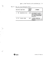
Page 51: ...al data set that is a peripheral connected to the works tation c 7 GND Signal Ground none Signal Gound provides a reference level for the signal voltages 8 DCD Data Carrier Detect input The data communications equip ment has detected carrier for example a modem senses tones sent to it by another modem over phone lines 15 DB Transmit Clock from DCE input Transmit clock from the modem This signal is...

Page 52: ...gnal Name Input or Description Output 24 DA Transmit Clock from DTE output Provides transmit clock from the Sun workstation This signal is usually not used for asynchronous devices most terminals printers modems etc 25 VERR reference 5V level none This signal is used by some modems to sense connection to the workstation 8 Revision A of 15 May 1989 ...

Page 53: ...C c ...

Page 54: ...e System 41 Workstation Power Down 41 Attaching the Wrist Strap 41 CPU Board Removal 42 B 2 Preparing the Board for Return to Sun 42 Removing the ID PROM 42 Removing the Data Ciphering Protocol Chip Set 43 Sending the CPU Board in for Repair 43 B 3 Installing the ID PROM and Other Chips 43 ...

Page 55: ......

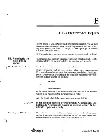
Page 56: ...system is powered down First warn all users that the system is about to be powered down Begin the power down procedure by changing to the superuser mode or to your root directory and then entering the command etc halt or etc fasthalt on the console keyboard This procedure ensures that any data in the buffers is written to disk before the UNIX operating system is halted After the SunOS is halted th...

Page 57: ...sed hex head machine screws that secure the CPU board in its card cage slot within the system chassis 3 Place the antistatic mat nearby on a fiat surface with the shiny side down 4 As illustrated at the left push the board extraction levers outward from the CPU board to back the board out a short distance 5 Carefully slide the CPU board the rest ofthe way out ofthe card cage 6 Carefully place the ...

Page 58: ...tched with 9518 The DCP PAL is located at coordinate H 24 and is etched on the top with 22Vl0 There are about fifteen chips labeled with 22V10 so carefully confirm the correct coordinate position before removing the chip For specific packing and mailing instructions please call 800 USA 4SUN When installing the ID PROM and other chips on the 3400 CPU board ensure that the V shaped cut in the chip i...

Page 59: ... ...

Page 60: ...c Power Consumption Tables Power Consumption Tables 47 ...

Page 61: ......

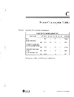
Page 62: ... Type SV S 2V 12V 12V Total Watts None 24 5 0 3 126 0 Hi Res Mono MG3 P4 25 5 1 3 0 3 138 Graphics Accelerator and Color Frame Buffer CXI P4 26 3 0 3 135 0 8 bit Color Frame Buffer Cg4 P4 27 2 0 3 140 24 bit True color CG8 P4 28 27 0 3 147 i Readings include Keyboard 3 Mouse 3 and Ethernet 47 Revision A of 15 May 1989 ...

Page 63: ... Buffer Type SV 5 2V 12V 12V Total Watts None 26 4 0 3 136 0 Hi Res Mono MG3 P4 27 8 1 3 0 3 149 0 Graphics Accelerator and Color Frame Buffer CXI P4 28 2 0 3 145 8 bit Color Frame CG4 P4 28 7 0 3 147 0 24 bit True color CG8 P4 30 9 0 3 158 0 Readings include Keyboard 3 Mouse 3 and Ethernet Revision A of 15 May 1989 ...

Page 64: ...a Review Draft 02 02 3 October 1988 Second Review Draft so 03 14 November 1988 Beta Review and Engineering Release so 04 23 January 1989 Review Draft so OS 29 January 1989 Beta Review A 10 17 April 1989 Released for customer shipment A 11 15May1989 FCS Revision A of 15 May 1989 ...

Page 65: ......

Page 66: ...we solicit your comments on the Sun 3400 CPU Installation Manual Part Number 800 2399 11 We would appreciate your telling us about errors in the content of the manual and about any material that you feel should be there but isn t Please list typographical errors by page number and actual text of the error Please list errors in technical accuracy by page number and actualteX tof the error Revision ...

Page 67: ...t but is not Is there material found in other manuals that would be more convenient if it were in this manual Did you find the organization of this guide useful Ifnot how would you rear range things Do you find the style of this manual pleasing or irritating What would you like to see different Mail this completed form to Manager Hardware Technical Publications Sun Microsystems Inc 2550 Garcia Ave...

Page 68: ... J _____ _ ...

Page 69: ... ...

Page 70: ... 7021 Europe Middle East and Africa 415 960 1300 England Korea 2 7802255 call European Headquarters TLX 37 29639 027651440 Nordic Countries 46 0 8 7647810 027651440 TLX859017 PRC 1 8315568 For U S Sales Office Singapore 224 3388 Elsewhere in the world locations call Australia 02 413 2666 Spain 1 2532003 call Corporate Headquarters 800821 4643 Canada 416 477 6745 Switzerland 1 8289555 415 960 1300 ...

Reviews: