15 of 42
•
Connect the end of the flexible hydraulic hose (3/8" JIC, F SWIVEL) to the
fitting at the cylinder.
DO NOT OVER TIGHTEN.
•
Connect the other end of the flexible hydraulic hose (3/8" JIC, F SWIVEL) to
the flow control on the powerpack.
4.5 ELECTRICAL
CONNECTIONS
CAUTION: ALL ELECTRICAL CONNECTIONS SHOULD BE MADE BY A
QUALIFIED ELECTRICIAN.
Refer to Figure 6, Electrical Diagram for electrical connections.
Electrical Breaker Size Recommendation: 20Amps
Figure 6. Electrical diagram for 230V/1 ph
4.6 CABLE
INSTALLATION
•
Remove the hydraulic cap from the fitting at the base of the hydraulic cylinder.
•
Depress the lowering lever on the powerpack, while using an air chuck to blow
air into the breather hole at the base of the cylinder to extend the rod.
•
Extend the rod until it reaches its full stroke.
•
Fill the reservoir on the powerpack with ISO 32 (10 Hydraulic Weight)
hydraulic fluid.
•
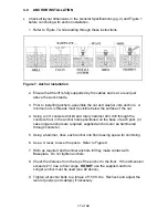
Install the threaded stud end of the cables to the tower top plates using the
7/8” Flat Washer, and two (2) 7/8”-14UNF Hex Nuts with Cable Spacers as
required (see Figure 3). The Hex Nuts, Washers and Cable Spacers are
located in polybag “A” (cables).
Summary of Contents for ALIGNMENT EELR124A
Page 8: ...8 of 42 TYPICAL BAY LAYOUT ...
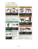
Page 23: ...23 of 42 6 0 SAFETY AWARENESS AUTOMOTIVE LIFT INSTITUTE ALI ...
Page 25: ...25 of 42 8 0 PARTS LIST 8 1 LIFT ASSEMBLY ...
Page 27: ...27 of 42 8 3 TOWER ASSEMBLY ...
Page 29: ...29 of 42 8 5 DECK ASSEMBLY LEFT SIDE ...
Page 31: ...31 of 42 8 7 CROSSMEMBER ASSEMBLY ...
Page 33: ...33 of 42 8 9 CYLINDER ASSEMBLY ...
Page 35: ...35 of 42 8 11 HYDRAULIC AND AIR KIT ...
Page 37: ...37 of 42 8 13 CABLE ROUTING ...


