18 of 42
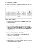
Figure 8. Floor slope
4 FT
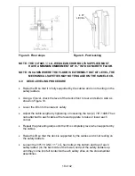
LEVEL
Figure 9. Post leveling
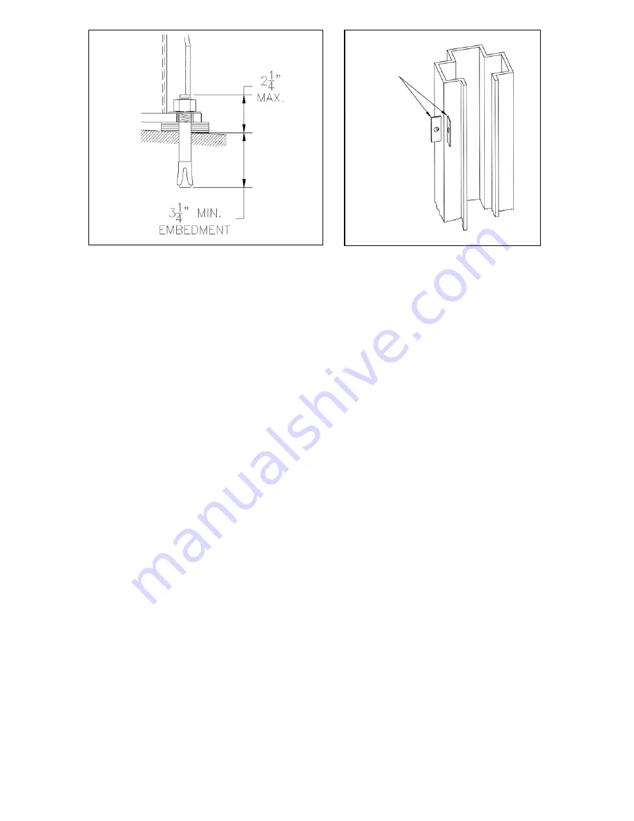
NOTE:
THE 3/4”
×
5 ½” LG. WEDGE ANCHOR BOLTS SUPPLIED MUST
HAVE A MINIMUM EMBEDMENT OF 3¼” INTO CONCRETE FLOOR.
NOTE: IN CASES WHERE THE FLOOR IS EXTREMELY OUT OF LEVEL, THE
MECHANICAL SAFETIES MAY NOT ENGAGE ON THE SAME LOCK.
4.9
DECK LEVELING PROCEDURE
•
Raise the lift so that it is fully supported by the cables and is not resting on the
safety ladders.
•
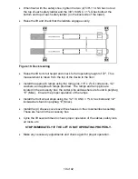
Using a 4’ level, check the level of the decks front to rear and side to side as
shown in Figure 10.
•
Lower the lift onto the nearest safety
•
Adjust the cable lengths by tightening or loosening the two (2) 7/8”-14UNF hex
nuts attached to each cable at the tower top plate to raise or lower each
corner.
•
Repeat the preceding steps until the lift is completely level when supported by
the cables.
•
Raise the lift so that the deck is supported by the cables and is not resting on
the safety ladders.
•
Loosen the 3/8"-16 UNC × 1" LG. hex bolts at the bottom and top of each
safety ladder (on the back side of the tower) and pull the safety ladders up
until they come into full contact with each safety shoe on the crossmember
assemblies.
Summary of Contents for ALIGNMENT EELR124A
Page 8: ...8 of 42 TYPICAL BAY LAYOUT ...
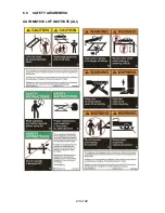
Page 23: ...23 of 42 6 0 SAFETY AWARENESS AUTOMOTIVE LIFT INSTITUTE ALI ...
Page 25: ...25 of 42 8 0 PARTS LIST 8 1 LIFT ASSEMBLY ...
Page 27: ...27 of 42 8 3 TOWER ASSEMBLY ...
Page 29: ...29 of 42 8 5 DECK ASSEMBLY LEFT SIDE ...
Page 31: ...31 of 42 8 7 CROSSMEMBER ASSEMBLY ...
Page 33: ...33 of 42 8 9 CYLINDER ASSEMBLY ...
Page 35: ...35 of 42 8 11 HYDRAULIC AND AIR KIT ...
Page 37: ...37 of 42 8 13 CABLE ROUTING ...


